
replacing a LCD suffering from zebra stripes in a Yaesu FT897
I bought this rig in 2006, and it is getting elderly. I have already had to replace one stock fault, the Toko ceramic IF filters, and now I get to deal with another stock fault, LCD zebra stripes. This seems to be a common fault with the FT897, and the FT857 which is very similar in terms of the pathology, though not the fix.
LCD zebra stripes, what they?
This is caused by the connection getting ratty between the LCD, the ribbon cable and some of the inline chips. You lose vertical strips of the display, and this gets worse with time. Maybe some of this is my bad, because I left the rig in an unheated and damp-ish shack for a while, but enough other people have experienced this fault for there to be a lively aftermarket in fixes. You get Youtubers who say fettling the LCD cable with a hot air gun, Qtips or magic incantations is a fix. It seems to be a temporary fix in some cases. Googling “yaesu lcd zebra stripes” seems to bring up mainly FT857 owners. This writer claims a permanent win using a hot air rework tool to reflow the lcd solder joints with a FT857. Although the FT857 is very similar in design and capability, the LCD is very different.
For the FT897 some friendy Chinese folk have reverse-engineered enough to get a display that works. There are several kits, they all seem to work along similar principles of intercepting some of the signals going to the original LCD and rewriting these in a small board for a different LCD. I bought mine from Aliexpress, we seem to have BG6ABD to thank for this one. On AliExpress the vendor jimaiqui supplies other screen replacements.
why fix this
Although the FT897 is old it occupies a slightly unusual niche. There’s no great 100W HF to VHF mobile/static portable replacement, the aughts seem to have been the heyday of the shack in a box. The FT991A is a nicer shack in a box but draws nearly 2A on receive, which is twice the power drain of the FT897Rx. You can easily get a much better rig, but not so much all in one. I’d have a much better radio capability, but at much more cost, power drain on receive and physical size.
The FT897 has a modest 700mA drain on RX compared to the FT991A and a good tolerance for sagging 12V PSU rails, probably from the design which could support internal NiMH batteries. The ever increasing urban noise at HF means it’s worth going mobile to get away from that racket, and since I don’t do Morse having more grunt than QRP is worth having. Though limited to 50W/20W on 2m/70cm respectively, this does SSB on these bands. There are many VHF/UHF FM rigs out there, but surprisingly few with SSB. So while the FT897 is pedestrian in performance by modern standards it would cost me a fair amount to replace the functionality. Hence there was an incentive to try and fix the problem, which is an increasingly hard to read LCD.
This is not an easy job and the risk of trashing your FT897 is very high
You have been warned, this is a tough job requiring fine soldering skills and a steady hand. If you can read the display acceptably, leave well be, this is a tiresome job with a high risk of failure. The zebra stripes did seem to be a progressive fault with my rig, but of course each year you leave it be you get another year’s use before the risky surgery. Hand soldering on a 1mm pitch is no fun, particularly across two board levels. Plus you have to mill a fair section out of the white plastic LCD holder because the replacement LCD is a good few mm wider and taller than the original. Get it wrong1 and you get to spit bricks on the vendor’s page.
I had to ask the vendor Jimaiqui for the instructions. They are in Chinese, though the pictures help you make an educated guess as to what to do. Note that there are several kits for this and not all of them are the same. Do not assume your replacement kit is the same as mine without verifying carefully, there are several variants of FT897 replacement display.
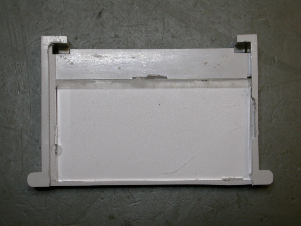
It was relatively easy to demount the front panel, and take out the three plugs from the rest of the rig which I then set aside. Following the Chinese instructions I removed the board from the plastic fascia. The original LCD looks like this
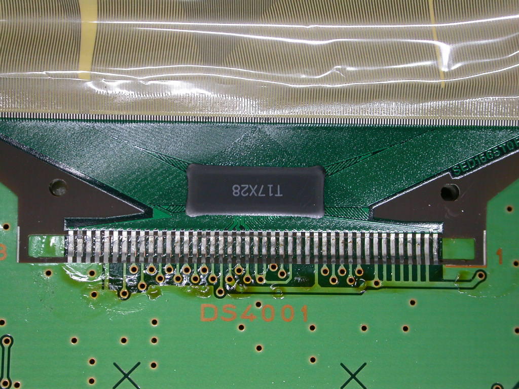
Yaesu use double-sided sticky tape to hold the ribbon cable to the white plastic LCD holder, I did not find it possible to remove this non-destructively, so I passed the point of no return early on, I was committed now.
You want to remove the replacement LCD while fitting the control board to the old LCD connection site, to stop it flapping around and getting in your way. It pays to lift the black clips of the cable clamp. This is not described in the instructions, unless it’s in Chinese without a pic.
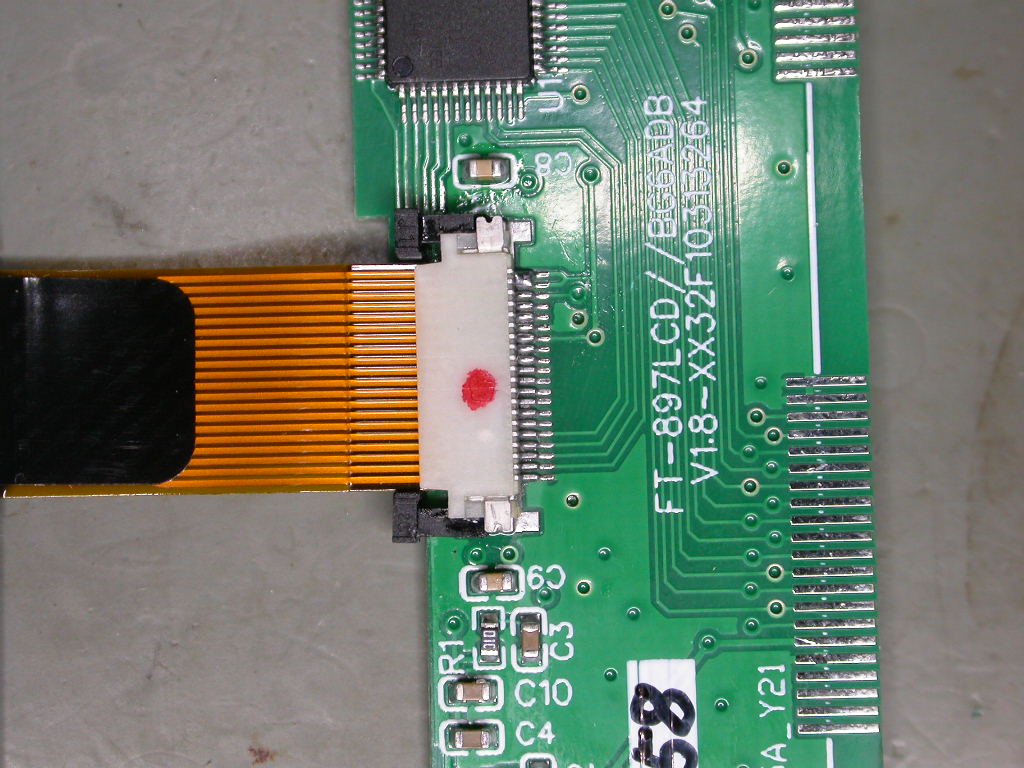
I attached the interface board guided by the picture in the Chinese manual, there is double-sided tape to hold it in place. There is an obscure instruction to chamfer the reverse of the white plastic LCD mount, this is the first of many abuses this unfortunate plastic piece will suffer. Turns out this is to clear the controller chip on the interface board and the LCD connector, and they do mean it, else the leverage will lift the other end of the board when you screw the plastic part back.
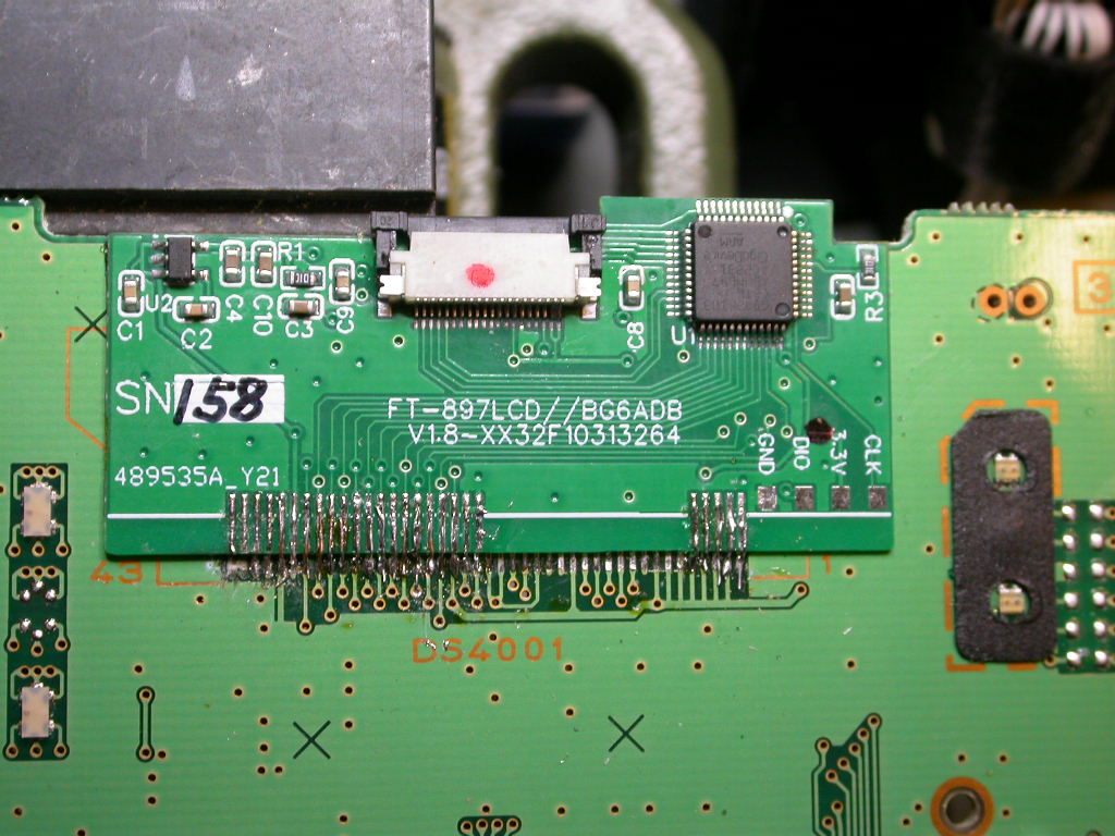
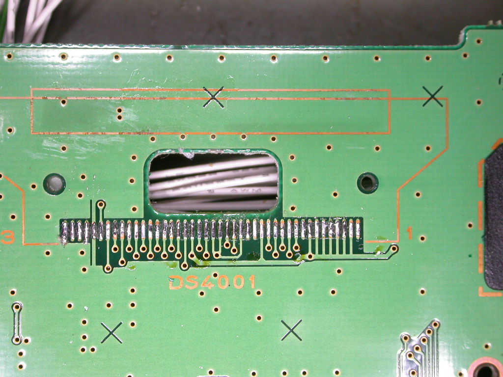
I’m not proud of the soldering, but these tracks are about 0.5mm wide. I used strands from some mains flex to bridge the different levels, this does not carry a lot of current thankfully. You can see I managed to lift the left hand pair of PCB tracks. This was my lucky day as these seemed merely there to anchor the LCD ribbon cable and carry no signals. But I buzzed these on the interface PCB and found NC so I persevered. I worked left to right (I am right-handed) buzzing each connection through, and also to the adjacent and previous track. I have a 2.25x desk magnifier lamp, and an Antex TCS iron with a No.107 0.12mm conical bit, the thinnest I could lay hands on. You really do want something with more magnification, professionals do SMD under a low-power microscope. So I got to work harder with visual aids that weren’t really up to the job.
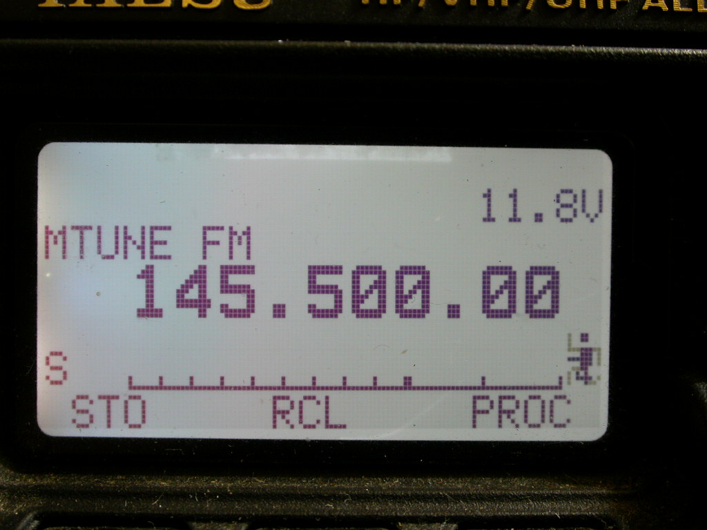
Once I had finished I patched the front panel connectors into the rig, with the LCD screen protection still there and had it in mid air. Applied power, and voilà - zebra-free visible frequency display text hanging in mid-air. Into the home straight, I thought, until I tried to marry up the LCD with the white plastic part, and discovered the display is too big by a few mm.
much mechanical fettling yet to be done
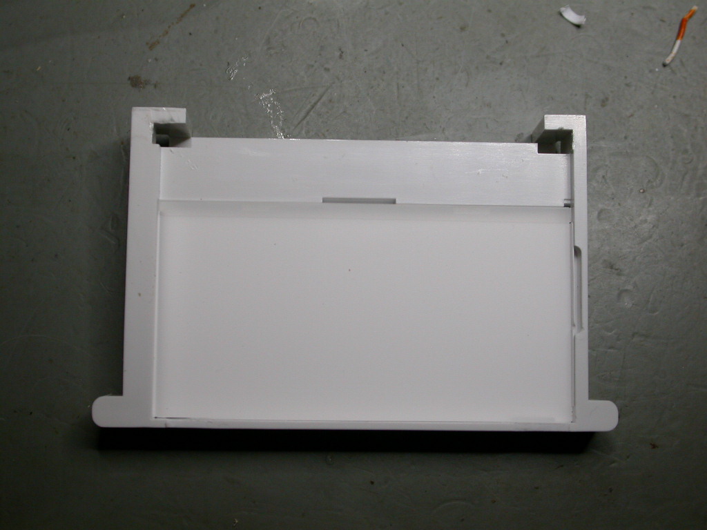
The Chinese manual suggests you trim off the excess with a knife, but I could see myself giving much blood doing that with a Stanley knife, so I used a Dremel with a routing bit in a pillar attachment and an XY table to mill off a few millimetres from the left-hand side and all of the bottom ledge of the plastic diffuser clip. They really don’t tell you just how much plastic you have to remove to fit the LCD glass. Even afterwards the LCD is a snug fit. Luckily the bit where I pressed too hard on the Dremel lever and gouged some of the trasparent diffuser is off the left had side of the display so you can’t see it. The Dremel Workstation is not a precision piece of gear, all that plastic… It sufficed in this case.
Time to refit the LCD and put everything back together again.
This is a fiddly and tiring job, it took me a morning to do. I did have visions of a secondhand FT991A to the rescue, but so far, so good.
the new interface board in use
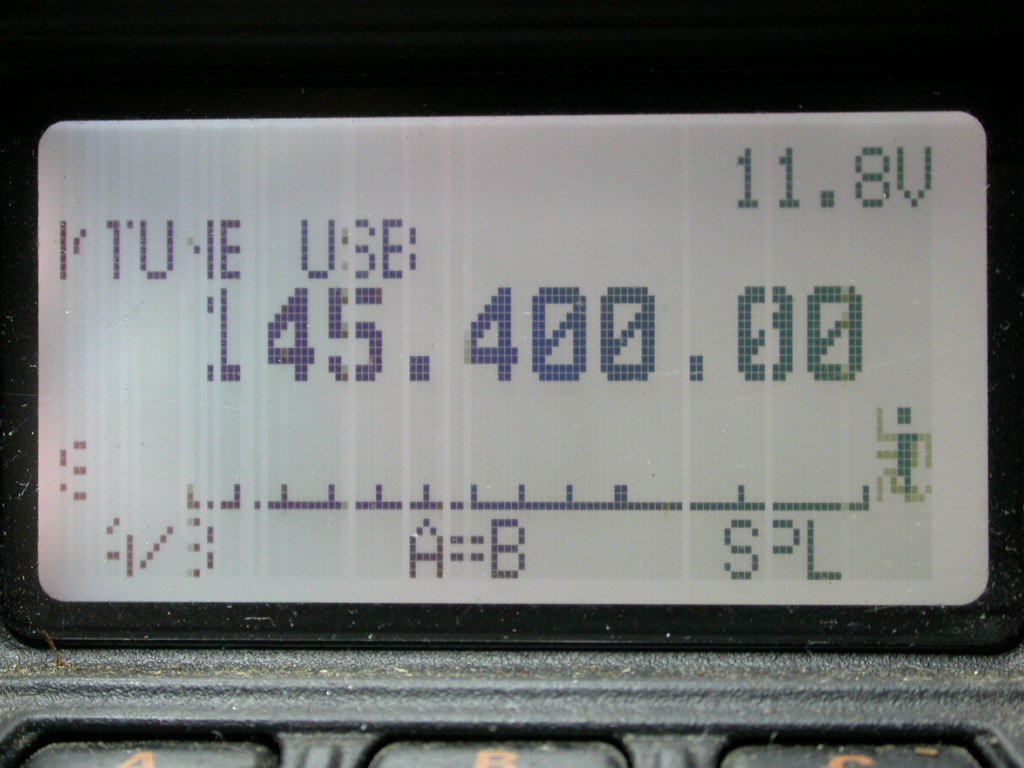
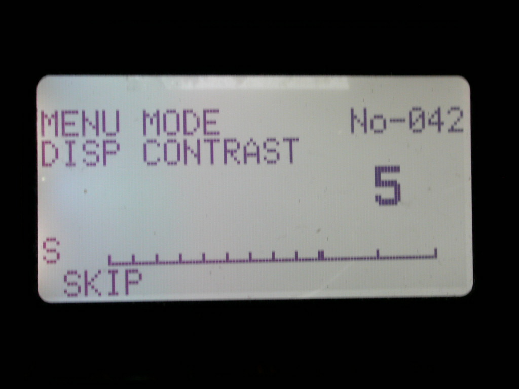
The interface board does a reasonably good job, with only the odd slight glitch - in the menu option where there’s a cursor
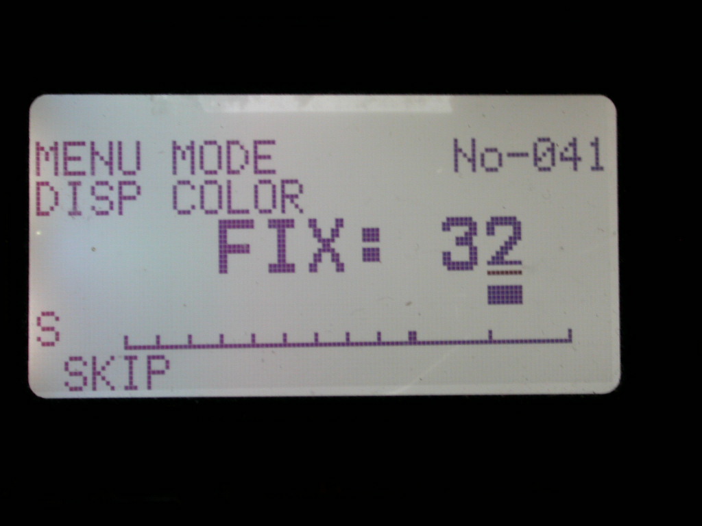
it can stick for the next menu option where it shouldn’t be
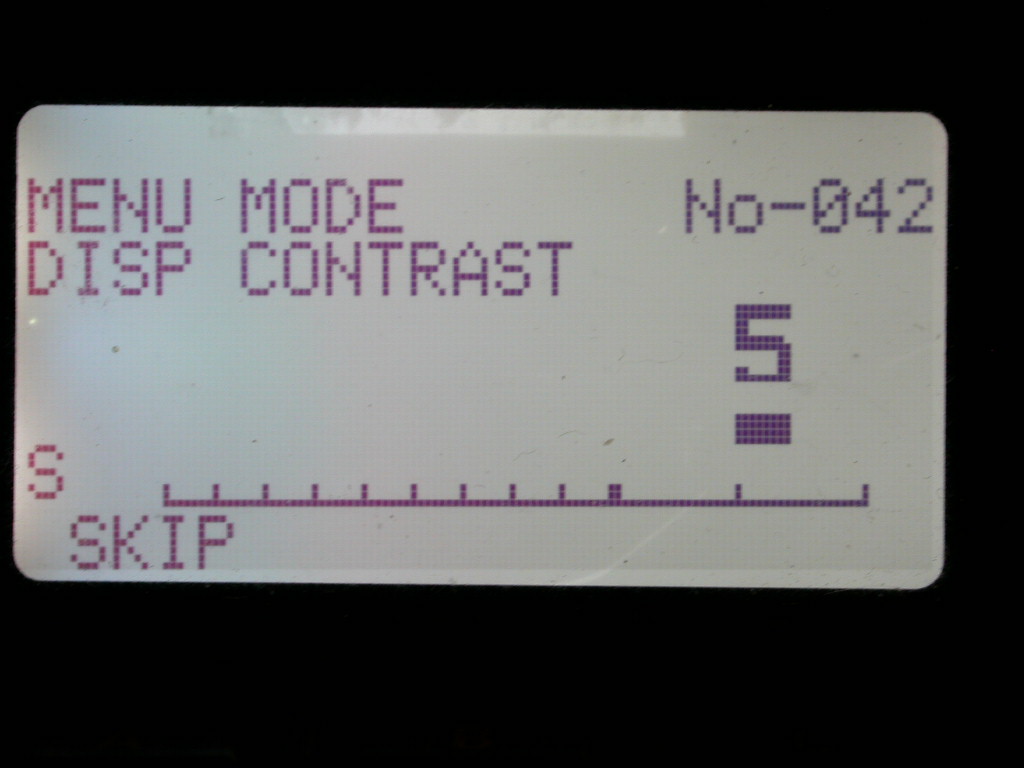
but it clears fairly quickly when another menu selection is chosen. This only seems to occasionally affect the menu settings, I haven’t observed it in the normal frequency display, and I observe no lag in the display compared to before, I don’t have any complaints about the responsivity.
So far this looks like a successful fix, and I now have it on soak-test.
-
it is possible the LCD was faulty, of course ↩