
replacing the ceramic IF filters in a Yaesu FT897
I bought this rig in 2006, and these rigs use three ceramic IF filters from Toko, which is/was a large Japanese manufacturer of RF components. Even the Japanese can have a bad day at quality control, and the ceramic filters in the Yaesu FT897 have a weird pathology. They are hygroscopic, or more specifically, the plastic case is, and seems to precipitate out salt crystals. Salt water and electronics is not a good combination.
get to know the enemy
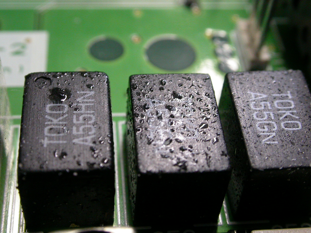
There are two schools of thought on what goes wrong with these, one is that Yaesu use diode switching to select which ceramic filter to use (AM, WFM,NFM, SSB/CW) but they put DC on the ceramic filters, and some folk say that’s bad for the ceramic filters. The other school of thought is that this is just a bad batch of filters. It’s pretty clear from the above picture that something is wrong with these parts. They really shouldn’t be sweating like that.
How do you know the problem? Crashes and bangs on RX and low sensitivity, the power meter waggling on tune-up.
This happened suddenly to me, I was getting ready for Exercise Blue Ham March 20/21, from my back garden due to it still being Covid-19 lockdown in England, I noticed tuning up was not steady, even switching to a dummy load, and investigated with a RSP-1A SDR. Where in previous sessions I had seen OK SSB, I saw my opposite sideband channel suppression fall to about 20dB. Nasty! I couldn’t in all conscience put this damn thing on the air so I switched to a KX3, which is a lovely receiver and a much better listening experience1, but only puts out 10W so it makes the other guy worked harder. I made 5 contacts
Contacts for G7LEE = 5
MRE51(5.335), MRE51(5.354), MRE19(5.304), MRE66(5.2785), MRE19(5.2785),
Hopefully the cadet stations were in lower noise environments than I am, so they could hear my puny signal 10dB down.
It’s fairly easy to get at the board these filters are on, you pop the top cover and you can see them. When I saw the state of those as in the pic above I knew this was the most likely problem, and the Radio Mechanic’s video goes through how to change them.
I bought my filter kit from Technofix, for about a tenner. I chose them largely because they at least seemed to know something about radio, but you can find these kits of three filters cheaper on ebay. It seems you can also buy them from Yaesu for only a little more.
is it worth it? A high risk of failure with small SMD devices interleaved with the filter pins
The trouble is this is a fifteen year old radio. It’s not worth paying someone to fix it, because after I’ve paid for their time and transport I am a fair way to a replacement transceiver. But on the other hand, it’s worth something to me in serviceable condition, so I took on this repair.
You need:
- replacement filters
- some heatsink grease
- decent solder removal
- a steady hand
- a magnifier
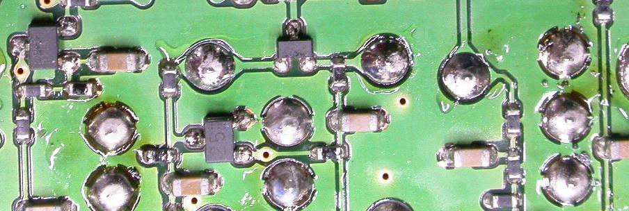
The problem with these filters is three of the pins are connected to ground through the double-sided PCB and there’s not really enough thermal relief on these pads. Solder removal is a bear. My 20 year old solder sucker wasn’t going to cut it, by the looks of the Radio Guy’s video. At the time I didn’t understand the construction of the filters enough to see if I could crush the filter and go in from the top. On the bottom of the PCB there are some small surface mount parts close to where you want to get into. Your mission is to desolder the through-hole parts while leaving those SMD parts well alone.
I figured I had an evens chance of success or less. But it was worth a go. Ideally I would have got myself a Hakko desoldering tool but at £300 I am more than a third of the way towards a Yaesu FT991 which would be a typical replacement so perhaps not.

So I opted for a Duratool soldering iron and solder sucker all in one gizmo. I can’t really say I felt good about this product, but it was surprisingly effective. And cheap, about a twentieth of the price of the Hakko. Reviews seem to indicate these are pretty much a use once and throw away device due to poor reliability, but this got the job done, so it doesn’t owe me anything now. I am now down about £25 on this project as I had to get some heatsink grease - the video helped me know I needed to get all these odds and sods before starting the job.
The Radio Mechanic talks about needing a small soldering iron tip, but the Duratool has a 2mm hole in the tip. Precision isn’t this thing’s middle name. However, by carefully studying the board and the SMD parts I was able to come in from an angle with this monstrosity that left the SMD parts alone, though it was a different angle for each pin.
Yaesu also use the hateful lead-free solder2 - my 50w Xytronic thermostatic iron found it hard to melt the solder enough to dilute it with leaded solder to lower the melting point on the ground connections due to the poor thermal relief on the pads. I missed the old Weller Magnastat irons I used to use in the lab at work. Maybe I should replace my poncey LED thermostatic iron with one of those old warhorses - for all their primitive design they did finesse and grunt in one tool.
I managed to get two filters out whole but this one I pulled the case off the top because the pins hadn’t desoldered right. So I got to see what’s inside, and it wasn’t a pretty sight:
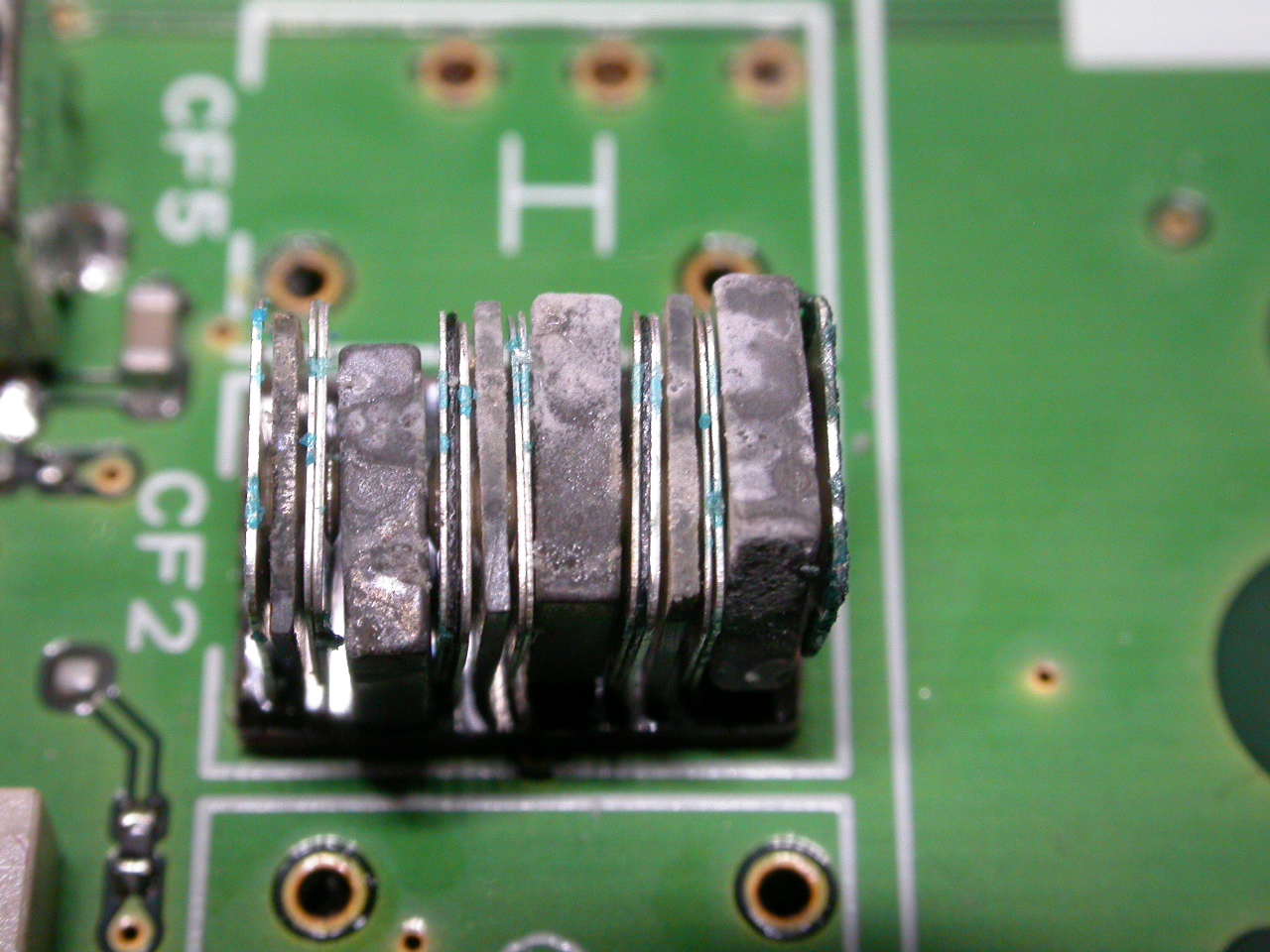
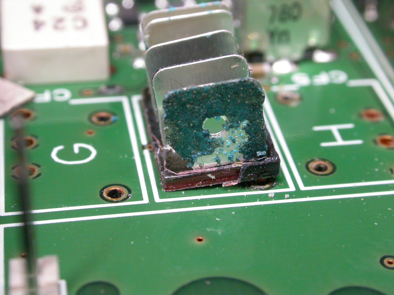
That corroded plate is the input (or output) terminal of the filter. I understand the wavering tuning signal now. In this transceiver the signal passes through these filters on both TX and RX - the filters take out the unwanted sideband, so as they get ratty you are short of grunt as well as losing opposite sideband suppression - because presumably the filter shape has gone to pot as well as having varying through loss.
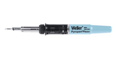
I fitted the replacement filters, again I struggled with the ground contacts. So I deployed a Weller Pyropen gas soldering iron with a 5mm chisel tip, and used just a corner of the tip. It doesn’t feel right to use that sort of thing on a SMD board, but it had the grunt, and I got away with it. I removed the flux with isopropyl alcohol, regreased the thermal paste and reassembled the rig. I sparked it up and listened to AM radio 4 on 200kHz 3 and a couple of medium wave stations, Volmet Shannon on 60m USB, GB3MCB at a shade over 100 miles away on 2m. I tuned up on 80m and on FLDigi I monitored my signal with the RSP-1A and was back to one sideband. I consider that a success for the investment of £25 and a couple of hours. Win.
how does an unused AM filter wreck your sideband reception?
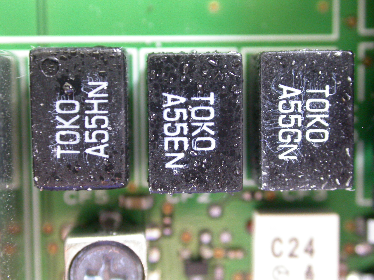
From the service manual A455H is CF1005 on the block diagram, passing AM, A455E is CF1002 doing WBFM, and A455G is CF1003 for NBFM. The great big shiny CFJ455K14 from Murata out off the left of the picture is doing your SSB/CW, which begs the obvious question, since you’re not using the damn thing, why does A455H knacker your sideband reception on HF?
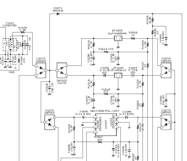
The offending filter CF1005 is at the top of this extract. Although the NBFM and WBFM filters also sweated, that signal path is not selected here, so they can stew. However, D1076 and D1078 (the dual diodes DAP222) either side select the filter path. To select a filter you pull both sides low DC-wise through the resistor networks - these are normally pulled high via 10k resistors to 8V, and a NPN transistor to ground pulls the other side of the 47 ohm resistors low to enable the path. This forward biases one or other of the dual diodes either side of the filter.
However, if CF1005 goes leaky to ground, eg from saltwater corrosion inside, I could see it pulling enough current to bias the diode on, even if the other signal path is selected - after all, 4.7k to ground is enough to switch on the diode in normal operation. So it will shunt itself across the SSB filter. Paradoxically if Yaesu had fitted series caps to the filter (as they did for the SSB filter) then CF1005 could rot away happily and you’d never know until you listened to AM. However, I am with the Radio Mechanic - what you really want is filters that don’t rot ;) And of course that only helps you on HF, unless you are a CW/SSB fellow on VHF/UHF. Your 2m FM channels are going through the A455G, though that didn’t look too bad on mine. I don’t think I have ever listened to Radio4FM on this using the WBFM middle filter. However, both of those are directly connected in a similar fashion to the 455H filter at the top, so a DC leaky rotting FM filter could pull down current through the diodes and barge in on the action even if the other one were good.
Similarly you can’t assume getting a better aftermarket plug in filter for the Yaesu to bypass the problem. The AM filter can still pull current through the diodes and shunt itself across your expensive mechanical filter, because of the way the diode switching works.
Testing this hypothesis - measuring the recovered filters
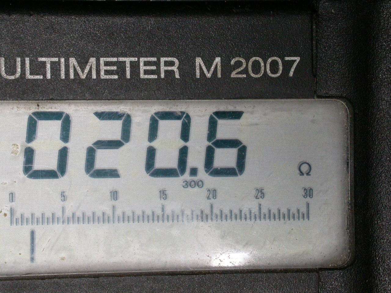
I measured the A55HN filter than I hooked out OK, it was about 11MΩ leaky end to end and some unstable ~1MΩ to 4MΩ one end to ground. There was no continuity between any of the three ground pins, implying either total failure or that you have to connect all these externally. The TGS Crystal spec sheet for the LTM455HW seems to expect a load resistance of 2k each side and a 3dB passband attenuation.
I put this between two 50ohm BNCs on a piece of copper PCB, and wired the terminals to the BNCs via 1.5k resistors, I figured 1k5 was close enough to the 2k nominal spec to get an idea of performance. I swept the filter manually using a signal generator. This one wasn’t bad, I hit the input BNC with 20V p-p which is probably rather more than it’s designed for, but makes it easier to get enough signal on the scope via a 10x probe on the output terminal of the filter across the 1.5k load resistor.
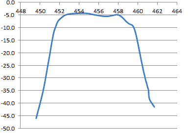
I can’t really argue with the performance if this, yes it’s a bit droopy on the HF side but for something with salt water in it it’s working well.
Not so much the A55GN. That measured 20 ohms to ground on one side. I was getting about 29dB loss on that at the lowest loss point of 453.9 kHz, it wasn’t really amenable to being swept using the scope voltage measurement. That would definitely be able to forward bias the selection diodes on it’s own.
Sadly I destroyed the AM filter A55EN in getting it out, which is what started me down this track, that will have been the one causing the static crashes and ratty behaviours on HF sideband. That was the middle filter, and the picture of the innards left behind showed that was well corroded too. So while I haven’t proven the hypothesis, I’ve certainly showed the A55GN could force itself in parallel with the working filter, 20 ohms to ground is less than the rig uses to forward bias the diodes (10k in the FM section, 4.7k in the AM/SSB demodulator) and will easily do the job.
The FT897 has value for static mobile because of its lower RX power drain due the now ancient superhet tech.
I hadn’t noticed poor performance on VHF/UHF NBFM because I hadn’t used this on 2m for a while. A shack-in-a-box sounded like a great idea when I started out but it makes 2m talkback on HF tiresome as you can’t talk back and do HF at the same time. It’s just not a great idea in practice often. Having said that for a single op or mobile the FT897 has some advantages running off batteries - without SDR/DSP it draws about 1A on RX as opposed to twice that much for a better specified modern rig, and you can read the display outdoors. It is cranky and old-skool, and it took me a very long time to get used to the menu structure. But for HF static mobile on leisure batteries it has advantages, and I am glad I managed to fix it. Here’s Outdoors on the Air extolling it’s specific virtues for that usage
-
I have only just done this repair, so I haven’t spent enough time with this on RX to establish whether in fact these filters had been getting ratty for a while impairing noise performance. The KX3 is a much less tiring listening experience than the 897, I had assumed this is because it’s much newer tech. On the short listening to both the 2m beacon and Volmet they sounded clearer on the FT897 than I recall, but that could just be propagation. ↩
-
As they are required to do by law due to the EU RoHS regulations. As a hobbyist I can use leaded solder but a manufacturer can’t. ↩
-
It should be 198kHz but I had this set to a 5kHz step size on AM. It was good enough to show no static crashes. ↩