
Crystal Oscillator For Intermediate Practical
The Amateur Radio training syllabus was changed last year, and the practicals are more extensive and more prescriptive. At Intermediate there is a new section
10C4 Demonstrate that a crystal oscillator is stable when subjected to reasonable temperature changes and mechanical shock.
that is as opposed to
10C5 Demonstrate that a variable frequency (LC) oscillator is not very stable when subjected to reasonable temperature changes and mechanical shock.
We are recycling the VFO from the previous Intermediate practical, which is a Hartley VFO and uses an air-cored coil and runs at 80m, because VFO stability is always easier at lower frequencies ;) So it would be nice if the crystal oscillator were in the 80m band too. The usual go-to 80m crystal is an American NTSC colour TV sub-carrier crystal at 3.579545 MHz, which are often used in other electronic gizmos where a stable frequency is required because these crystals were made in millions so they are cheap.

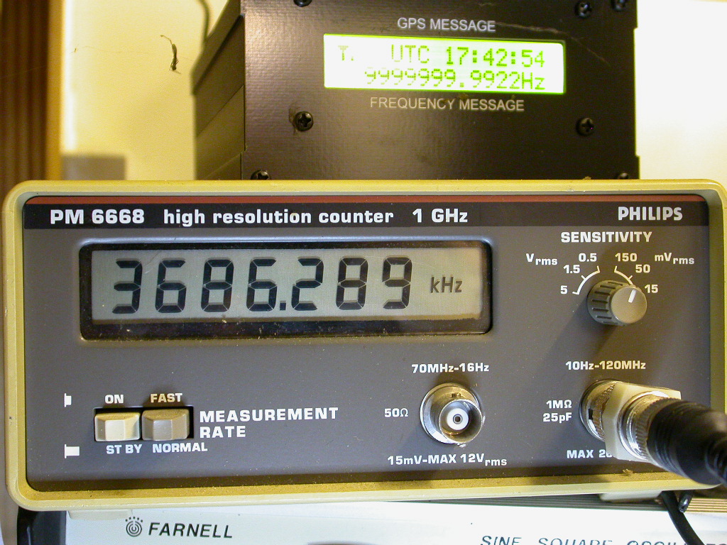
As it was I couldn’t find a US subcarrier crystal in my junk box, but I did find a 3.6864MHz UART crystal 1, which is in the SSB segment of the 80m band.
I used a Colpitts crystal oscillator, taking the values from the venerable Crystal Oscillator Circuits2 by Robert Matthys. I used the FET variant on page 36, this is basic enough as no great demands are being made of this oscillator, all it has to do is be better than the VFO. Matthys takes some of the guesswork out of setting the capacitors in the Colpitts design.
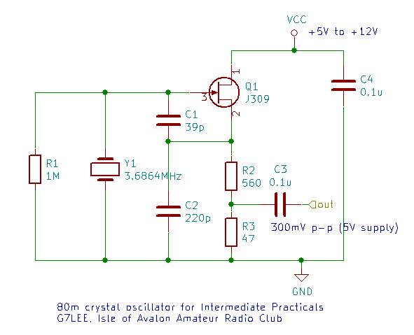
Rather than use a buffer I have taken a ~50Ω tap down the source resistor. This should reduce the effect of external loading, make the source impedance closer to 50 ohms and reduce the output to less than 0dBm so it shouldn’t harm a receiver if connected straight to the output. I used a J309 FET, though a 2N3819 would be fine (with different pinout).
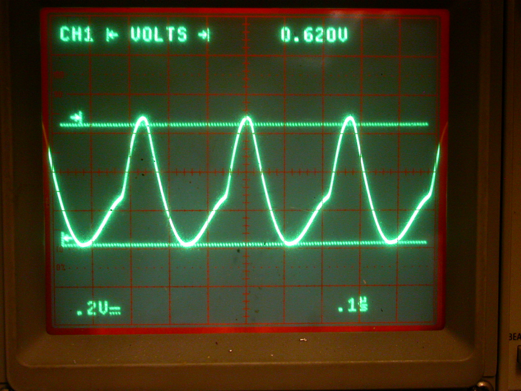
As you can see, there are some harmonics in the output, since it is not a pure sinewave. This gives us the opportunity to show the value of using a low-pass filter - I will use the one from the 80m WSPR filter for Raspberry Pi for the following parts of Intermediate:
10C6 Find at least the 2nd and 3rd harmonics from an RF oscillator by using either a receiver or spectrum analyser.
10C7 Demonstrate the reduction in harmonics by using a low pass filter or AMU, measured using either a receiver or spectrum analyser
-
These were made for serial UART chips - divided by 12 they give 307.2kHz, which is 16x the 19.2kBaud clock frequency - dedicated Universal Asynchronous Receiver Transmitter chips used this 16x clock frequency to oversample the incoming signal. ↩
-
Crystal Oscillator Circuits, by Robert Matthys, publ Krieger 1983 rev 1992 ISBN 0-89464-552-8 ↩