
Modifying low-cost Moonraker HB9CVs
The Club’s portable, low-power multipurpose station consists of a rucksack containing an FT-817ND (Collins SSB type), an LDG Z-817 automatic ATU and LFP batteries.
For HF a Spiderbeam Aerial-51 provides up to seven bands (two of them dependent upon the ATU). For VHF and UHF any suitable antenna can be connected to the rig’s front panel BNC socket.
Because of the local geography it would be interesting to try to cover the Glastonbury area from a station on the Mendip hills a few miles to the north, a vertically polarised beam antenna giving a wide beam being suitable for working experimental mobiles and handhelds in the test area.
G7LEE having some time ago donated two Moonraker brand HB9CV antennas for 2m and 70cm these were thought suitable for such an experiment and have been modified for portable work in vertical polarisation.
The 70cm antenna was modified first. The long boom was boldly sawn off and a heavy spring clamp fitted using cable ties to allow the antenna to be quickly attached to the plastic top section of a portable mast.
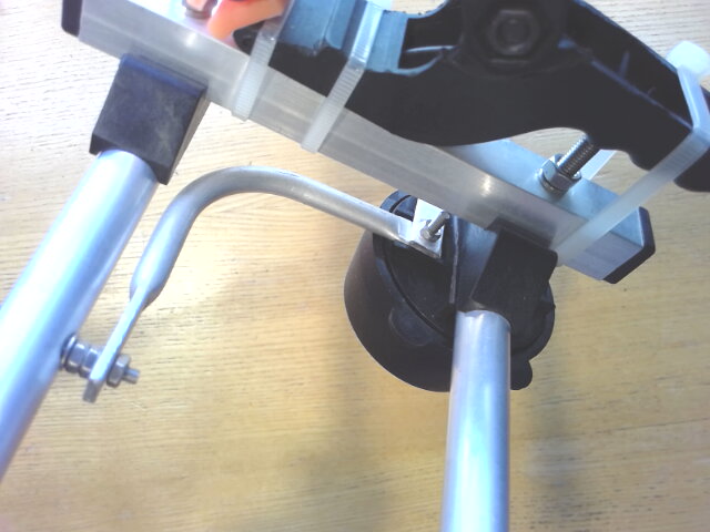 The 70cm antenna’s feedpoint
The junction box feeds the HB9CV’s double-gamma matching system off centre and contains a series 30pF variable capacitor of the common Philips ‘beehive’ type.
The capacitor is fed from a BNC socket fitted to the box and grounded to the boom. Using a separate feeder like this is not normally desirable as the BNC plug and socket always introduce losses of their own but for /P operation was considered justified by its convenience and durability and by the low losses in the short feeders.
On testing and adjusting for minimum SWR with an antenna analyser the 70cm HB9CV returned a quite acceptable SWR of 1:1.37 at 435.4MHz and was put to one side.
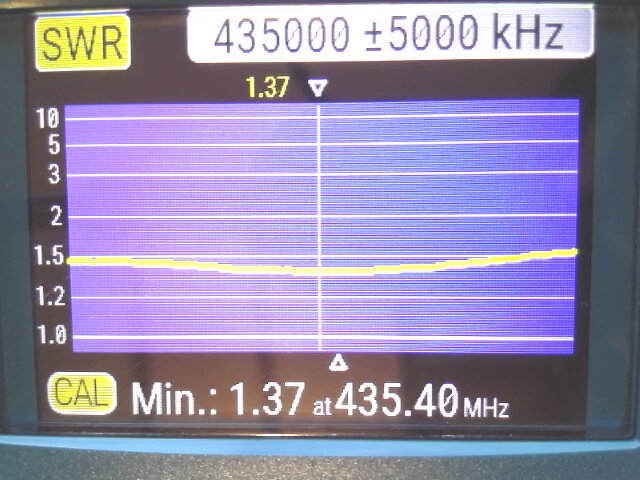 70cm HB9CV SWR test result
Next the 2m antenna was assembled from its kit, not without some difficulty as its double-gamma rod is a rigid single piece and quite tricky to position onto three screws at once, whereas the 70cm one is in two pieces and easily bolts together. As soon as the 2m one was together it was taken to pieces again to be modified.
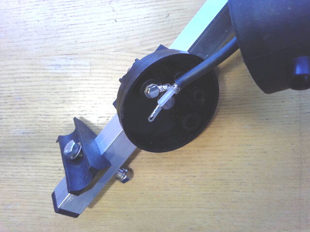 The mysterious piece of coax
Messrs. Moonraker had not seen fit to provide a proper variable capacitor for this kit. Instead a piece of coax rather like RG-58, about 280mm long and stripped at one end, had been soldered by the braid to the boom tag and strapped to the boom with rubber bands. A second, unstripped piece of coax of the same length was also provided.
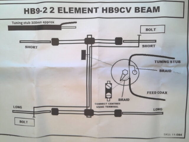 The instructions
 describe the piece of coax as a ‘tuning stub’ but it seems to be intended as a capacitor made of RG-58, since it is wired where the series capacitor ought to be in an HB9CV.
RG-58 having a capacitance of about 82pF/m this capacitor would have a value of about 23pF until one started cutting pieces off it to lower the capacitance in order to tune the antenna. Then having gone too far one could strip and install the other piece of coax and proceeding more soberly do the job again, only properly this time.
Abandoning this entire system as value-engineering taken too far a 30pF Philips capacitor was obtained and installed instead, along with a BNC socket, which was difficult only in arranging the capacitor and its connections to fit comfortably in the junction box. In the end the capacitor’s longer side leg was cut off and the shorter one crimped and soldered into a small ring terminal which was then bolted to the feedpoint, a slightly different arrangement from the 70cm antenna.
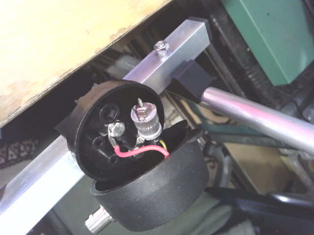 Inside the junction box
This after some adjustment of the capacitor gave the very satisfactory SWR of 1:1.04 at 144.5MHz and was then left alone.
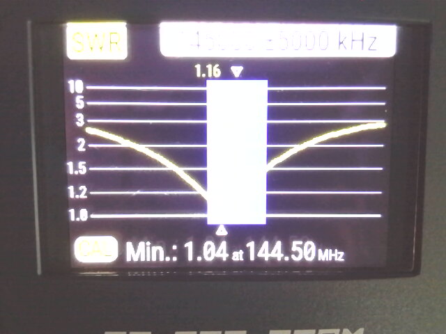 The 2m SWR test result
Remaining to do on the 2m antenna: sawing off the boom and fitting a clamp to attach the antenna to the mast.
These two vertical HB9CVs might come in handy for something in the short term, but if not there will be more on this project when we get around to testing the entire /P QRP rucksack system (‘he said, confidently’).