SAQ loud and clear in Glastonbury on Alexanderson Day 10:00 and 13:00 UTC
SAQ is a mechanical low-frequency TX at 17.2kHz, designed in the 1920s to send telegraphy across the Atlantic, over an open-water route, to Riverhead, Long Island. Grimeton was the transmitter site only. Reception was done at Kungsbacka.
Today was another chance to hear this veteran TX. The signal was received quite clearly.
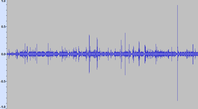
An 8kHz sampled copy of the audio signal from the 10:00 transmission received indoors in Glastonbury
For the second transmission at 13:00 I moved outside
testing a few changes.
I used SAQrx as described in the last post together with a ferrite rod antenna, tuned directly to 17.2kHz. It’s hard to qualify changes when you only have the signal for a quarter of an hour every few months, I changed several things. Note that unlike previous times, I have used the 300Hz CW filter of SAQrx rather than the 1000Hz filter. This does improve the clarity of the signal to my ears, but the difference is not due to a technical change I have made to the antenna.
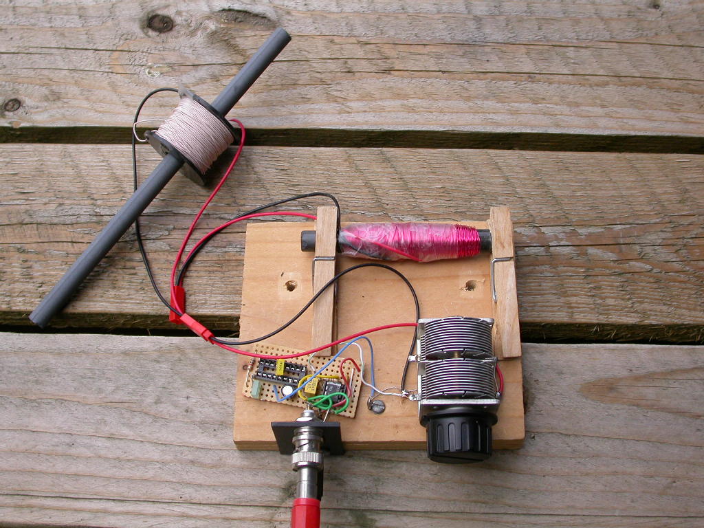
Compared to last time I used a longer 200mm ferrite rod. You never really know what you get from China, this one is listed as MnZn ferrite. I used a reel of Litz wire 130 strands 0.04 and lazily took advantage of the fact the hole in the middle matched the ferrite rod reasonably well. Litz wire is dear, at £20 for this reel by far the dearest component. It didn’t make a huge difference - I think the original design with many turns is fine if you’re looking for a low cost solution, perhaps use the longer ferrite rod since the marginal cost is low, it discriminates a little better against ambient QRM. The signal is still 598, the 8 is the audible frequency variations, which probably wouldn’t impair copyability, but I can only pick out a few characters, which is due to my lack of skill not a technical issue ;)
Coil Q measurements
I measured the -3dB points from a loosely coupled coil about 30cm away driven by an oscillator, to this ferrite rod (with the Litz). They were 17.07 and 17.32 kHz, when the coil was resonated with (2n2+470p+~350p) = 3nF capacitance. The system Q is about 68. For the red coil I measured the -3dB points at 17.1 and 17.32 kHz, giving a Q of about 78, resonated against the capacitor on its own about half meshed at about 150pF. These are respectable but by no means anywhere near best practice. Ben Tongue (see literature search) achieved Qs of nearly 1000 using MnZn rods around 500kHz.
The Spectrum Lab Rx filter bandwidth of 300Hz implies an overall filter Q of 60, though a much better shape factor than a single tuned circuit. That does, however, warn that I don’t want to optimise this tank circuit Q too much more, a Q of 1000 would give me a passband of 17Hz, which would give smeared out Morse copy and SAQ’s relative frequency instability will push the operating margin even more.
line up transmissions
There was some preliminary tuning1 from SAQ done before 09:00 UTC, where you can hear the faint changes in frequency in the down-translated signal. This is not a crystal oscillator or even a LC tuned circuit, it is a high-speed spinning disc driven at full output power with mechanical frequency control. To keep the load on the ‘oscillator’ more even they dump some of the power into a water-cooled resistor on key-up.
I also received their line-up transmission at about 09:58 UTC indoors
compared to the same line-up just before the second transmission, with the receiver outdoors. This line-up was shorter, it was hard to conclude a difference between outdoors and indoors, though I found the message a little clearer outdoors.
you can hear the variation in tone due to the speed variations of the alternator.
Reducing the impulse noise - noise blanking?
Looking at the signal waveform, the biggest thing that I thought would make a difference here is a limiter. There’s no real fading on the signal. I have a recording of the raw signal so I played with this in Spectrum Lab which has a noise blanker, since the selectivity of the ferrite antenna is useful but much wider than the wanted channel, ideal for the IF input channel for a noise blanker.
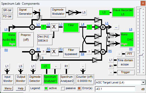
SpectrumLab is hard to use, but there is a SAQ Rx preset, and I was able to feed the signal into that. Sadly, with the default SL noise blanker threshold of 20dB I couldn’t really hear or see any difference, lowering the threshold did cut the noise but made the signal sound choppy. Looking across the spectrum
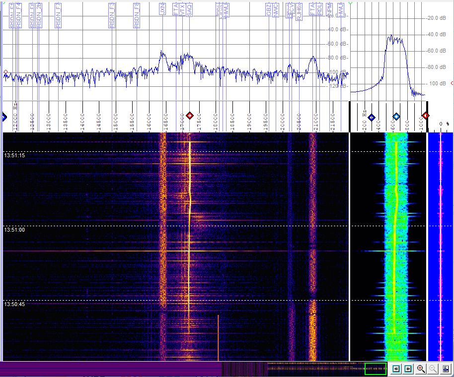
the peaking of the coil does lift the 17.2kHz signal and the noise peaks of the QRM centred on it, but loading this 96kHz sampled RF input signal into Audacity shows it only peaks at -18dBFS so it is not overloading.
Spectrum Lab limiting reduced the impulse noise
I tried a limiter set to the average level of the signal, again placed between L1,L2 in Spectrum Lab, and this was easier on the ear and less spiky than SAQrx’s AF decoding. The signal fed in to Spectrum Lab is SAQrx’s 96 kHz sample rate RF recording, there is no difference in the source. Spectrum Lab did a better job of the USB downconversion even before the limiter was used, there was less impulse noise.
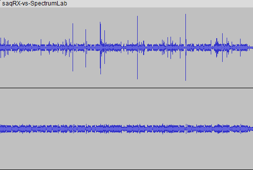
I have run the decodes in tandem on this stereo recording with the SAQrx panned hard left and the Spectrum Lab decode panned right. I roughly matched the CW tone and use a similar 300Hz CW filter bandwidth. This is of the early tuning signals and the repetitive vvv vvv vvv SAQ
Ideas for improving the ferrite rod
Designing with the ferrite rod seems to be a black art, indeed R.H.M. Poole of the BBC R&D Department2 said that
The theory is easy to apply for simple loops and whips, but unfortunately the presence of ferrite complicates matters greatly — so much so that an analytical treatment appears not to be possible.
and you see some quite heroic empirical attempts to combine many ferrite rods to improve medium wave DXing.
There as some ferrite rod users3 who think electrostatic screening might help. The rod input is at a high impedance at resonance so this may be an issue, needs experimentation. You tend to lose Q shielding a loop, even if you avoid making a shorted turn, but since the ferrite rod is a preselector rather than the main filtering component I can live with that.
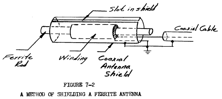
I tried this on the red original coil, using aluminium foil grounded to the tuning capacitor chassis. It lost about 10dB of signal (and noise) and shifted and broadened the tuning. This stacks up with adding stray capacitance and reducing Q. It seemed to reducing some of the impulsive noise, particularly broad-spectrum noise starting lower than 17k. It’s possible to hear these noise crackles on the 96kHz signal, so these static crashes must be very strong to get through the tuned circuit far down the slope into the AF region - the recording peaks at -18dBFS so is not overloaded4. Naturally I can’t hear the wanted signal at 17kHz ;)
I line up on the Russian station RDL at 18.1kHz rather than wait another six months for SAQ. RDL comes on and off, letting me see what the quiet channel looks like too.
SAQ livestreams
Below is the SAQ livestreamed video of the alternator being started and the first transmission
followed by the second
ferrite rod literature search
The CIA report (p 13 ff) seems to indicate that for optimal Q the winding should extend along most of the length of the ferrite rod, I had been caught out assuming that the air-cored rule of thumb of similar length to diameter was optimal for Q, hence trying to get away with the spool as supplied.
Set against this, the BBC white paper favoured shorter coils about 0.4 times the length of the rod, and most of the MW coils I have seen are like that. However, the BBC was aiming at HF reception, and the increase in number of turns was not good for them. I could use all the inductance I can get, to raise the L/C ratio for such a low frequency. Philips 5 seem to favour the coil length of about half the rod length, and they probably knew more than most about ferrite rods in radios, though again at MW and LW frequencies rather than VLF. Ben Tongue’s work 6 indicates
about 77% of the maximum Q is attained with a core about 2.4 times the length of the solenoid with the turns number, solenoid size, core length, etc used here. About 68% of the maximum inductance is attained. Note also that when the length of the core is shortened to approximately the length of the solenoid, Q drops precipitously. Resistive losses are mainly proximity effect losses. Hysteresis losses are magnetic losses in the ferrite core itself. Total losses are the sum of the two. There is a good lesson to be learned here: To maximize Q, do not cover the whole length of the core with the solenoid.
which supports the BBC and Philips case, as well as the value of using Litz wire, to make a coil about half the length of the rod. At these low frequencies, that shows the longer rod has value in raising the inductance while keeping the coil short enough. I have much to learn / experiment here ;)
Ben Tongue has another interesting snippet, which I have no way of substantiating
Note: An easy way to use a DVM ohmmeter to check if a ferrite is made of MnZn of NiZn material is to place the leads of the ohmmeter on a bare part of the test ferrite and read the resistance. The resistance of NiZn will be so high that the ohmmeter will show an open circuit. If the ferrite is of the MnZn type, the ohmmeter will show a reading. The reading was about 100k ohms on the ferrite rods used here.
This is fair enough for the Rapid Electronics ferrite rod, which was sold to me as a NiZn material and indeed shows no response on a DVM. The longer rod I purchased from ebay was advertised as MnZn but also measures o/c on a DVM, implying NiZn. For low frequencies I would prefer MnZn with its higher permeability, but I get to live with what I can get retail.
-
the tuning signals were taken from SAQrx before I used the limiter with Spectrum Lab, so they have the impulse noise that Spectrum Lab processed better for the main signals) ↩
-
BBC Research & Development White Paper WHP 091, Ferrite Rod Antennas for HF?, R.H.M. Poole, 2004 ↩
-
I can’t logically rule out perhaps there were HF peaks that aliased down to audible frequencies, this is a laptop sound card that probably isn’t really designed to record from the mic input at 96kHz. ↩
-
Philips Technical Review January 1955 Vol 16 No7, p191 ff “The Ferroxcube antenna (ferroceptor)” ↩
-
Ben Tongue, Q of ferrite rod inductors.. ↩