
T2LT antenna for CB and 10m
M0JII brought along a T2LT1 antenna he had constructed for 11m CB, so I thought I would give it a try on the club CB net, UKCB channel 34, and later on I tried it on the 10m net
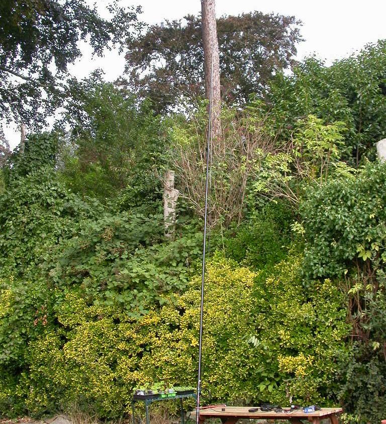
M0MCX has more on the T2LT. It appears to be as much art as science because you need good coax and have some consideration of the velocity factor, but even then some folk have it and some don’t. There’s some thought that these are sensitive to the environment around them, but they are good for rapid deployment and a stealth antenna, it was hard to get a useful picture ;)
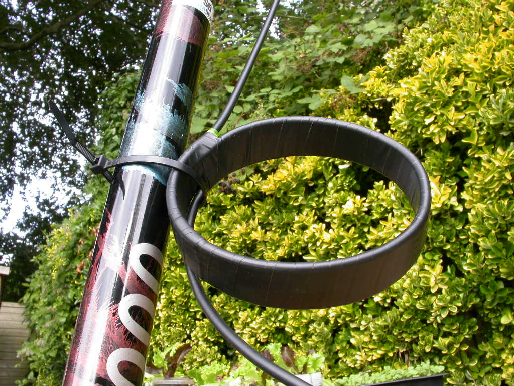
People seem to have mixed success making these. Basically you peel λ/4 of braid from the coax, mark another λ/4 below the peeled part, fit the T2LT RF choke, and off you go. The devil is in the detail - what is λ/4 with your coax velocity factor? If you take a lead from the flowerpot antenna which is the same sort of thing, then the length of the coax with braid part wants to be about 2% shorter than the top section, but the overall λ/2 antenna length is only shortened by ~10%. rather less than you’d expect from the typical coaxial cable velocity factor. And the choke needs to be resonant - 5 turns on a 4” sewer pipe is about there with RG56 for 10/11m, but as ever YMMV2.
Similarity between the T2LT antenna and the flowerpot antenna
The 2m flowerpot antenna, as used on the Beacon Batch 2m SOTA activation, is another example of the T2LT principle, and has the same finicky setup of the choke. Having seen the Smith chart on this 10m antenna, I wonder if that would be a better way of tuning the 2m choke, and indeed T2LT chokes in general, to try and get some of the black art out of the choke winding3, it is easy to spot the resonance on a Smith chart and hopefully optimise it.
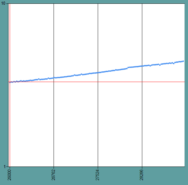
This is more tuned for the EU CB channels than 10m and the UK CB channels, but it is still a serviceable SWR of 2:1 on the UKCB band
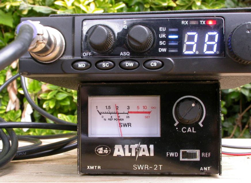
I had decent results readability 5 on 4W FM out to Tony in Bridgwater about 11 miles away, which isn’t a bad result at all on CB, and I was received with good readability 5 at Weston SDR. I used a Team ME-4 with stock mic.
10m net trial on 28.405MHz
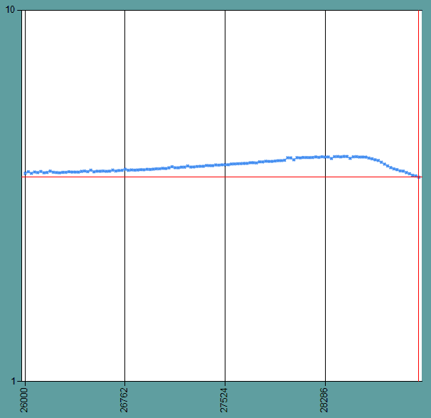
On the 22 Sept 10m net I rigged this through an ATU switchable between the Antron A99, retuned to 28.405 MHz and the T2LT. The ATU improved the over 2:1 SWR to about 1.3:1
The tuner meant I could switch rapidly between the two antennas, which were rigged withing 20m of each other and with about a 1m difference in height AGL favouring the Antron. In this way I was able to determine that M0JII in Bridgwater 11 miles away on a relatively unobstructed path was a S7 on the T2LT and a S8 on the Antron. There was more difference in favour of the Antron to 2E0OSS who is closer but with a hill in the way, from which I infer the pattern of the antennas differed, but this was not very consistent, unlike the path to Bridgwater. The T2LT is a good choice for a quick temporary rig on this band, though it probably wants to be remade tuned for 10m. That may have value as the sunspot activity rises and 10m comes out of the doldrums.
It would be a great stealth antenna, but in practice for a fixed install water is going to run down the exposed inner and work its way into the coax somehow, I can’t see a way of waterproofing that, unless you use a radome made of 15mm plastic water pipe or 20mm conduit, which rather defeats the stealthiness.
SWR measurements
The T2LT antenna has a rep for finicky construction. The cable choke is all that separates what should be a high-impedance end of the antenna from the cable sheath - after all this is a continuous piece of coax bar the choke. Investigating it with a MFJ-226 analyser for sensitivity shows the antenna wants to be in the clear and unmolested by detuning elements, such as an operator. Experimentation shows the choke is very critical to detuning, though it does a good job of isolating the feeder from the antenna itself.
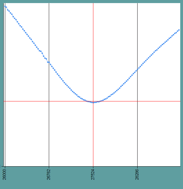
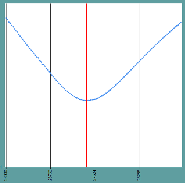
The SWR is not riveting at 1.54 even at its best frequency 27.54 MHz, in the gap between EU and UK channels. It’s serviceable, however, 1.7 at UK40 and 1.8 at EU1.
Smith chart of S11
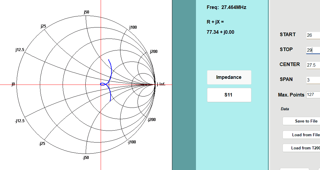
The Smith chart shows why SWR bottoms out at ~1.5 - the impedance at resonance is 77 ohms
-
Since you asked, T2LT is short for Tuned Transmission Line Trap. This is from a German patent from 1939, but as M0MCX says the patent surrounds only the use of a tuned choke which has a capacitor across the choke for tuning, not the actual antenna. The term T2LT is perhaps a misnomer
this is because the tuned element is the trap - here the inductance of the 5 turns of coax resonate with the inter-turn capacitance to make a resonant Tuned Transmission Line Trap. more ↩
-
Harry’s Law of coils applies 1) You cannot wind coils like I, and I cannot wind coils like you. 2) Coil-winding data is a constant that varies from person to person. ↩
-
On my 2m flowerpot antenna I optimised the choke by making trial chokes out of the cable and looking for the resonance in S11 of the choke measured from one end of the braid to the other end in isolation using a VNA, and then replicating the optimised choke in the length of cable used for the FP antenna, before making the antenna itself from the free end after the choke. ↩