
developing a ferrite rod receiver for SAQ at 17.2kHz
SAQ is a mechanical low-frequency TX at 17.2kHz, and usally transmits a signal on Alexanderson Day, the next one is Sunday, July 3, 2022. Unfortunately they were unable to do so this year, which takes the heat off this project, though there are other sources of LF signals that can be used to test it. SAQ was designed in the 1920s to send telegraphy across the Atlantic, over an open-water route, to Riverhead, Long Island1. Generating 17.2kHz mechanically is a seriously brute-force operation
Somerset is not an open-water route, and the world has become a lot more electrically noisy at low-frequencies than 80 years ago. However, we are much closer to SAQ than Long Island, and signal processing has improved a long way. Paul over here has a nice summary of the various options for receiving SAQ. You can use an e-field whip but I was drawn to his approach of using a ferrite rod, as commonly used on long-wave and medium-wave. Atomic clocks on 60kHz also sometimes use a small ferrite rod, so there is some prior art. What is less common, however, is a good theoretical basis for making a ferrite rod aerial outside the usual medium and longwave applications. There is Alan Payne’s paper2 which seems to indicate this is not a trivial exercise. For the typical MW radio use and a 350pf-ish cap and a 1cm rod diameter a rough guide is about 60 turns. It seems you can use more ferrite to get more signal - see ferrite sleeve loop antennas at SWLing. This BBC R&D paper looks at ferrite rods but for higher frequencies 3
The UKRAA has a project tracking these VLF stations for sudden ionospheric disturbances4, they tend to favour frame aerials in the urban environment, monitoring the NATO station Ramsloh in Germany on 23.4kHz. A good description of this is to be had at physicsopenlab
I haven’t had much success with frame aerials either :( So I passed on that option.
Hardware
I have some ferrite rods from Rapid Electronics - they are to be had from ebay, but the trouble with components from ebay is that there is only a loose connection between the descriptions and what you get. At least I have a sort of datasheet. Since my ferrite rod is not ideally optimised for low frequencies, so winding involves cut and try, the datasheet did not inform me deeply. In an ideal world you would use MnZn rather than NiZn5 and get more inductance per turn and therefore a higher self-resonant frequency. You can buy MnZn ferrite rods on ebay, but whether you believe the description is up to you.
I took inspiration from Paul
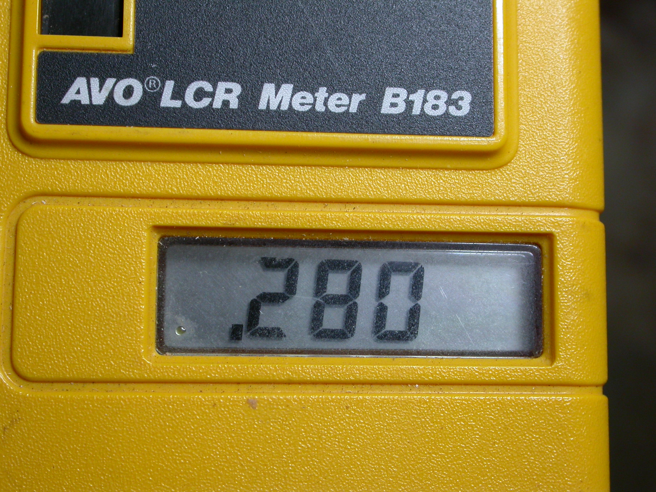
We need a lot of windings: around 900 (!) to get to a inductance of 82mH. A bit more or less is not important.
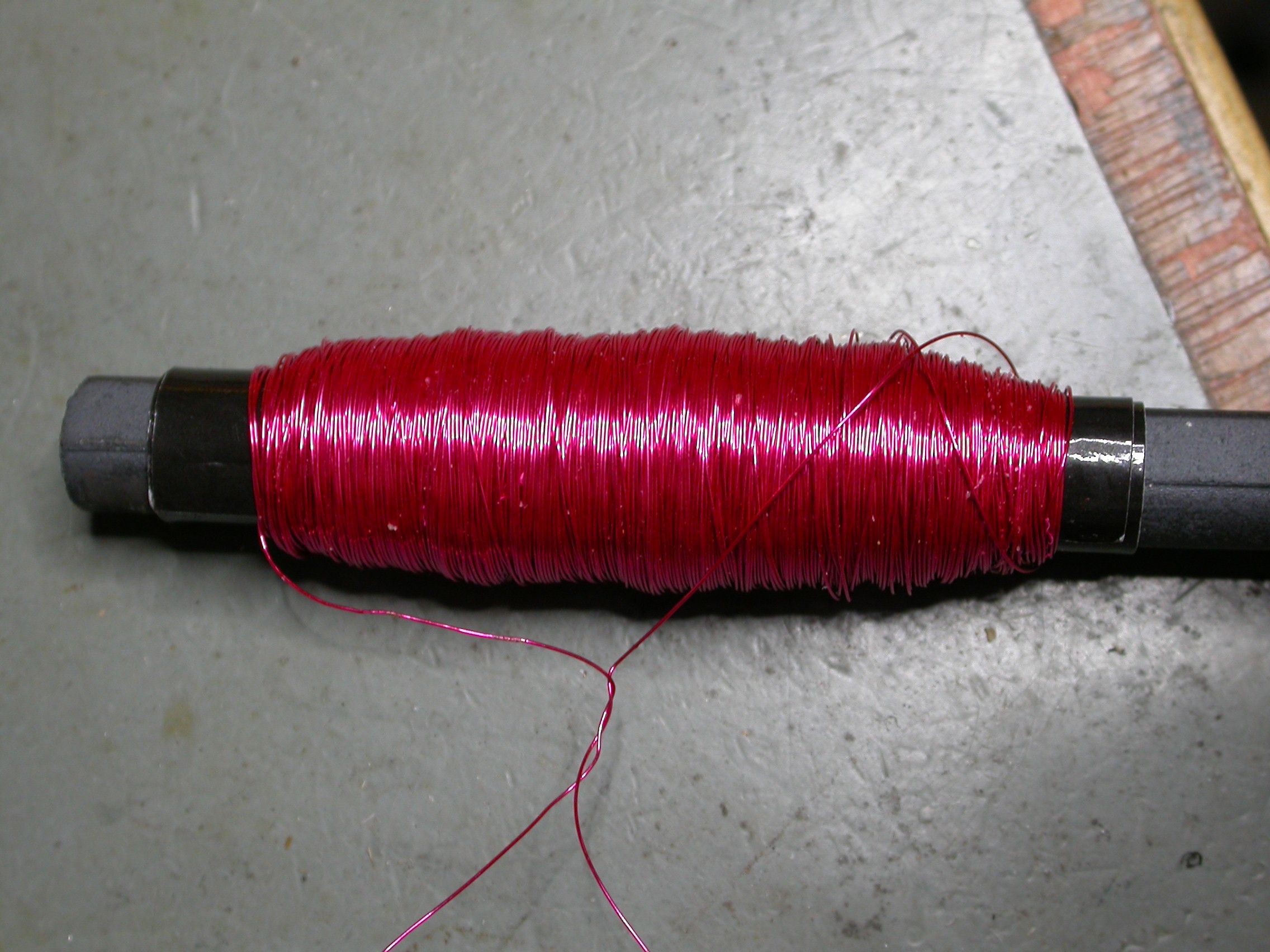
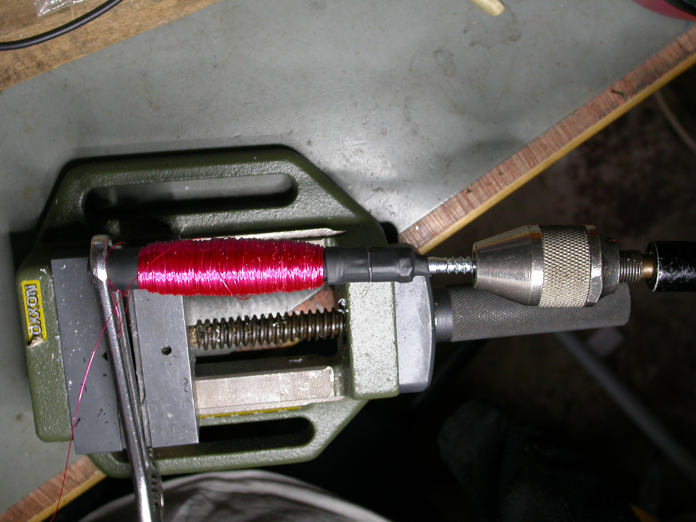
but I aimed at more turns. This IET paper6 seems to indicate the received voltage increases with the number of turns, although that makes the parasitic self-resonance fall in frequency. I scavenged the wire from some previous experiment, so I wound all of it onto the ferrite rod using a Heath Robinson contraption using heatshrink and a hand drill. I have wound coils using an electric drill, but it felt like a good way to smash the fragile ferrite rod, and the feed bobbin had tape on some of the layers, slower was better to keep control.
Energising the coil from a ferrite-cored inductor mounted about 5cm aways driven by an audio oscillator induced a visible signal in the coil placed across a 10x scope probe, showing the self-resonant frequency (SRF) to be a measly 29.4kHz. Adjusting drive to make the signal 100mV p-p then sweeping the drive to find the ~70mV p-p points showed the -3dB points to be 20.37 and 28.61 kHz, showing a Q of about 16.
Previous generations would despise the lack of ambition for high Q values here, and had to optimise Q because it determined selectivity. This is only my preselector, so I will start with this for maximum signal, since for me selectivity is defined in the FFT in the computer program used to downconvert. It is always easier to remove turns than to add them. The signal will be fed into a PC sound card, most of these have an internal sampling rate of 48kHz, so 24 kHz is the highest carrier frequency that can be processed, so the SRF does not prevent me investigating other signals. I can remove turns and add C if I feel I want a higher Q at a later stage. If you look at high-Q coils from up to about the 1970s, you see the coils wave-wound into pies with gaps between then, to reduce self-capacitance. This is not something you can do by hand with a drill. Lloyd Butler VK5BR did rather better than I did breaking his hand-wound coil into pies, but he used a ferrite rod twice as long as mine. He seems to have achieved a SRF of > 52kHz and an inductance of > 100mH.
I made a simple 2N3819 FET based amplifier for this, and discovered I had to remove some turns because the 2N3819 input capacitance lowered the resonant frequency. Not as low as SAQ, but I wanted to be able to get as far as 24kHz, the Nyquist limit.
It is usual to bypass the source resistor to get the highest gain, but in my case the stray drain/gate capacitance interacts with the tuned circuit to make a 25kHz oscillator
Software
Sabine DL1DBC has a nice page on the updated version fo SAQrx where you can download the windows program, which lets you tune the LF band and decode the CW audio. I used SAQrx v0.98. I started it up with the output of the FET buffer wired to the mic input of a laptop, via a TRRS to headphone and mic spitter. DL1DBC favours e-field probes and there is nothing wrong with that, he is near Dortmund, about 750 km away from Grimeton, I am about 1200km. The original destination, Radio City in Long Island, NY, USA is about 6100 km, a much bigger ask. I have failed several times using e-field whips, because they are very susceptible to noise in urban areas - previous attempts with SAQ using e-field probe in the garden and a SDR resulted in 100% failure rate, showing nothing but every SMPS in the area. So I was keen to try something else.
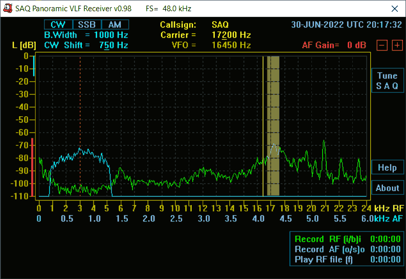
I didn’t expect much, this was indoors on the window sill. But I saw several carriers for the government VLF signals. Tuning the capacitor gives a worthwhile 20dB heft to the signal+noise floor. It gets me convincingly above the apparent noise floor of the microphone preamp, which is usually fairly average in a laptop motherboard.
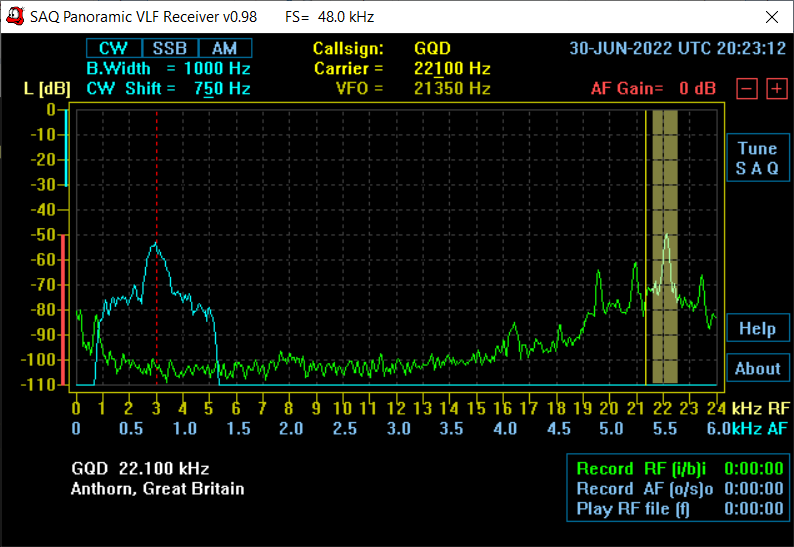
tuning GQD gave me a rewarding nearly 20dB signal to noise ratio, which was promising.
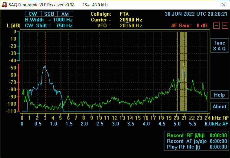
and reorienting the rod gave good reception of FTA. Using a random Chinese switched mode power supply gave me an ugly result
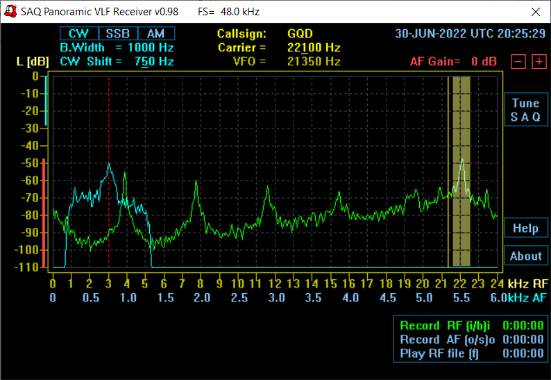
There are now two routes to the mains, capacitively coupled, which show battery operation of the preamp scores. The results are nevertheless very promising, showing easy reception of four VLF stations at ~ 20dB signal to noise ratio, indoors with the ferrite rod aerial and no special measures to get away from the RF hash from a lot of switched-mode power supplies in the urban environment.
a second time round the loop
DL1DBC says that SAS on 40.40 kHz uses the same antenna as SAQ, so if I could receive SAS then I am likely to be able to receive SAQ. To do this I need to set my original coil aside and wind a new one with fewer turns, and switch the sound card sampling rate to 96kHz. It’s a shame I can’t get to 192kHz wher I could get MSF but the PC won’t do that, but it will do 96kHz, you set that in the sound device properties, had to set it down to 48kHz to try SAQrx first.
The second mod I can try is to use a CA3140 MOSFET opamp for the active device rather than the FET.
Update. This worked in November, using the CA3140
-
Described in The Book of Radio, Charles Willian Taussig, 1922, page 312ff. The American TX was at Radio Central and Rocky Point, Long Island, and used similar Alexanderson generator. Modulation was achieved through saturating an iron core with DC or not, to control the HF drive signal, using the nonlinearity fo the iron core allowed a relatively small DC current to control the 100A carrier wave going into the tuning system of the antenna, the presence of DC reducing this to 3A. ↩
-
Payne, Alan G3RBJ. (2021). Self-Resonance In Ferrite-Rod Antennas (Issue 2). More on the transmission-line theory of self-resonance ↩
-
UKRAA receiver manual here https://www.ukraa.com/downloads/manuals/vlfreceivermanual_v2-pdf/user-manuals-release/vlfreceivermanual_v2-pdf ↩
-
https://kormag.co.uk/what-is-the-difference-between-nickel-zinc-and-manganese-zinc-ferrites/ : MnZn materials have a high permeability, while NiZn ferrites have a low permeability. Manganese-zinc ferrites are used in applications where the operating frequency is less than 5 MHz. Nickel-zinc ferrites have a higher resistivity and are used at frequencies from 2 MHz to several hundred megahertz. MnZn would be the way to go here then, but I used what I have ;) ↩
-
Design of a ferrite rod antenna for harvesting energy from medium wave broadcast signals, Dyo et al, 2013 DOI https://doi.org/10.1049/joe.2013.0126 ↩