Yaesu FT3DE mic connector pinout and wiring
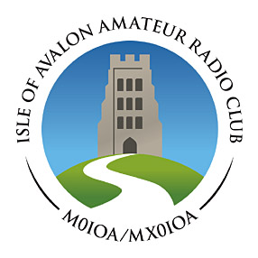
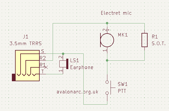
I have a Yaesu FT3DE with on-board APRS, FM and Fusion/C4FM. I wanted to plug an external mic into it, and use an earpiece for the audio. Because: SOTA among other things. Also the internal speaker isn’t that great. They make a big song and dance about the rig being sort of water-resistant, but that tends to go with rubbish speakers. My aim was to end up with this
It was harder work than I expected. Normally a hand mic is basically electret mic, SPST switch, maybe a socket for the earpiece, wiring, job done. Once upon a time, manufacturers would tell you the mic pinout. but Yaesu don’t now. In the advanced manual, they tell you to go buy an optional Microphone Adapter CT-44. I didn’t find that much on the Web about it, apart from the hint that Yaesu have used just about any connector and any pinout over the years. This works with my FT3DE1. To save you the ~£10 cost of a CT-44 and the extra hassle/unreliability of more connectors in the field2, you need a 3.5mm TRRS jack. Wiring is as follows
| Pin | Function |
| T | RX audio to LS |
| R | N.C. |
| R | Mic/PTT |
| S | GND |
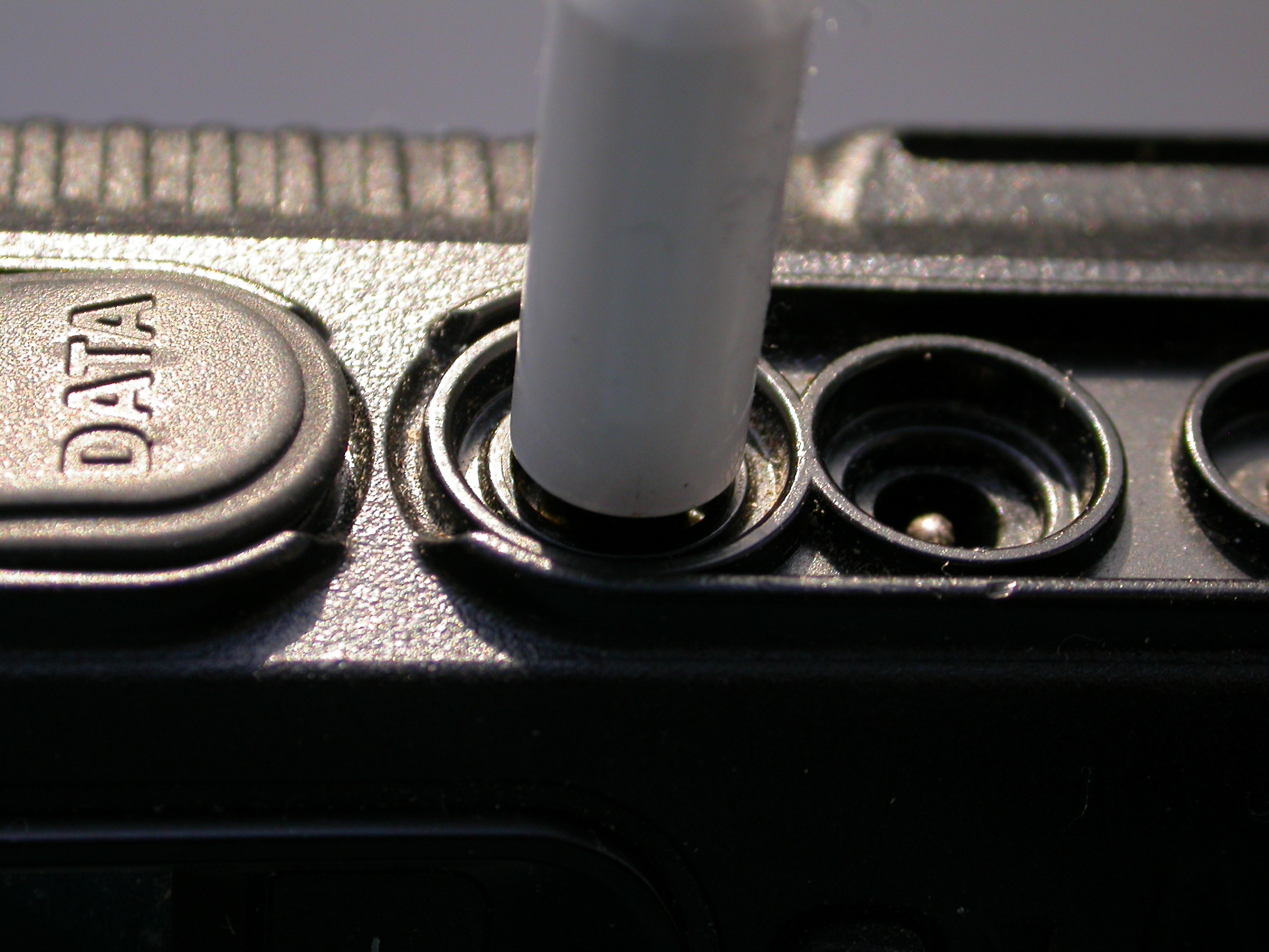
but wiring this was still an exercise in frustration. For starters, it uses the infernal series mic/PTT configuration, but it’s fussy about the electret, whch needs to draw enough current when enabled. The rig is also fussy about the mechanical design of the TRRS plug, which is recessed, thugh at least there’s a reason for that, which is to accommodate the rubber water resistant cover. Which I unscrewed and put in a safe place within half an hour of getting the rig, because you can’t charge it easily with that in place.
Too many gotchas out to getcha
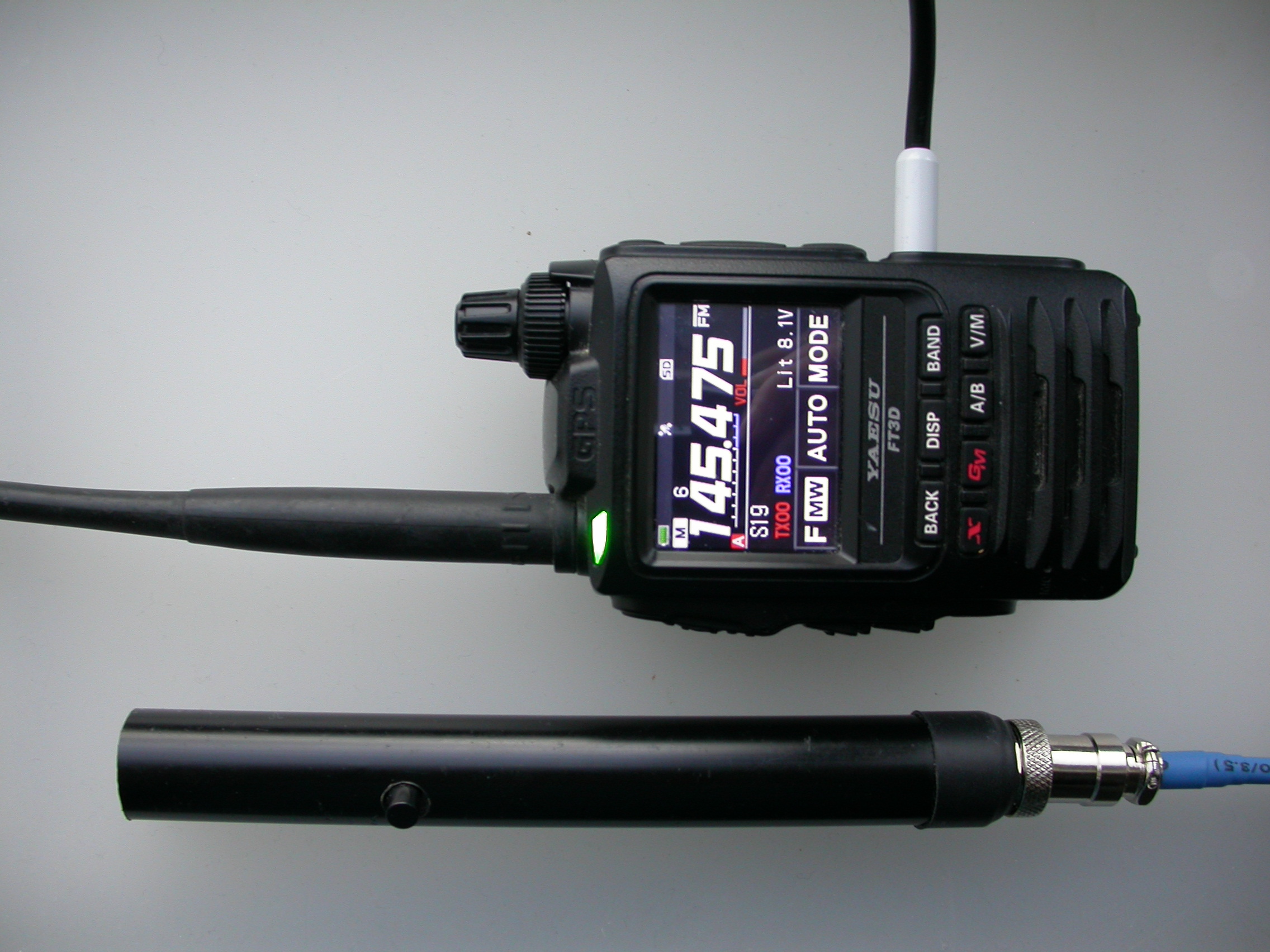
First off the bat, get a slim 4-pole 3.5mm TRRS jack. Ebay was my friend here, the slim jack is often needed for phones which also take a 3.5mm TRRS jack.
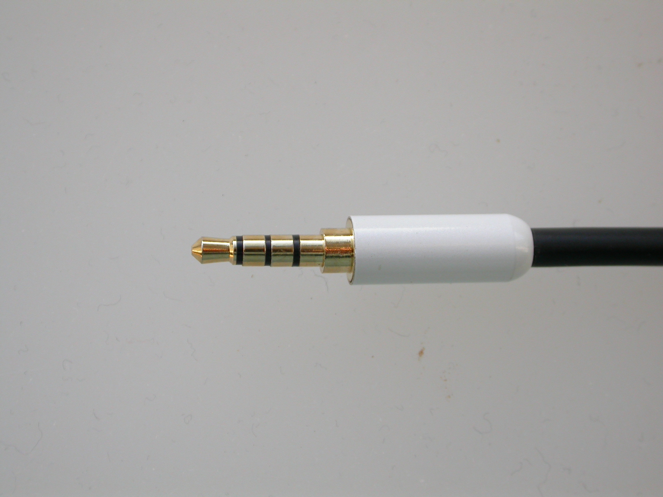
This is the one I got. A slimline jack is a bear to solder, natch. You can get TRRS jacks to flying leads which saves you that pain, but now you have to get a slim enough jack with flying leads. The reason it has to be slimline is this.
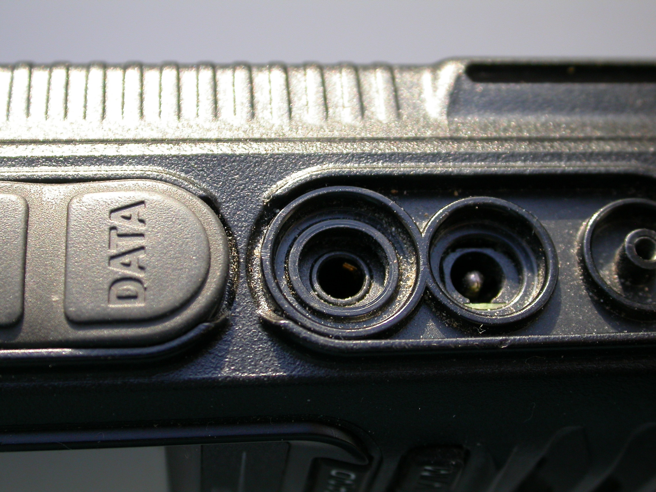
Darn. really should have blown out the swarf from filing some plastic which got everywhere ;)
So much for the mechanicals.
electronics - a series HT mic arrangement, with a gotcha
I wired this up, and I could hear OK but pressing the PTT gave a blip of carrier and then nothing, back to RX. I bought a cheap Chinese earpiece mic and measured across sleeve and the nearest ring, observed 890Ω with PTT pressed, o/c PTT released. Measuring my mic, I observed 1.36kΩ pressed, o/c released. The values you measure will be different, it depends on the design of your DVM, but it showed me there was a measurable difference, and which way to go. I used a fairly cheap Chinese electret capsule, I bought a job lot of 10 for less than £1. Cheap capsules normally draw more current in my experience, but these are clearly not rubbish enough ;)
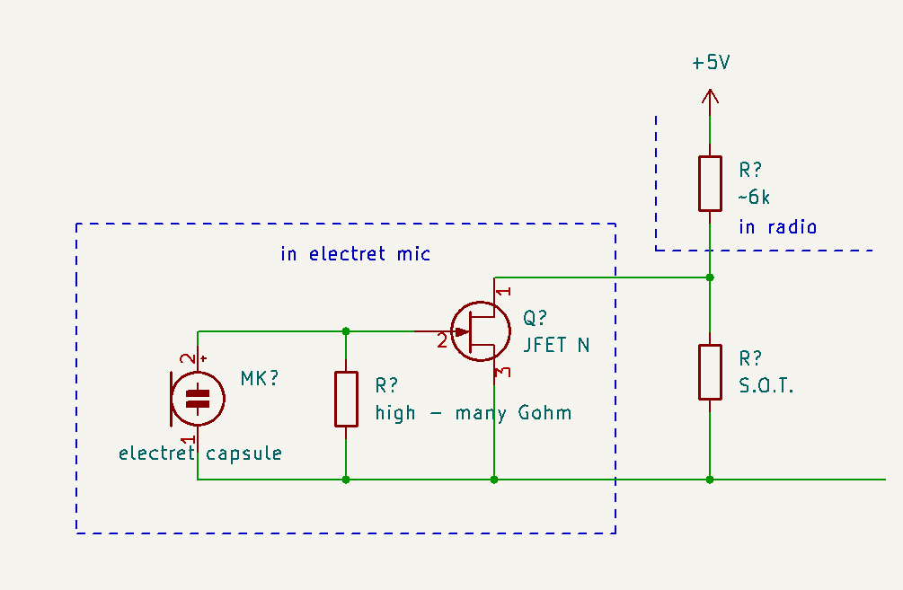
So I shunted a resistor across the electret, select on test (S.O.T.). 10kΩ was too high, no change. 8.2kΩ was enough for PTT to work, so was 6.8kΩ and 3.9kΩ. Usually an electret mic goes to an arbitrary drain resistor of about 6.8kΩ to 3-5V and the output is developed across that resistor, so to a first approximation the higher the resistor the better, not to shunt too much of the signal away. I settled on 6.8kΩ, on the grounds that the FET in the electret mic is somewhat temperature sensitive so I don’t want the absolute highest value I can get away with, give a bit in hand for drift. I measured the voltage across ring to ground with PTT pressed, and it was 2.6V with no resistor, about 2V with 8k2 and 6.8kΩ, and 1.8V with 3.9kΩ. Presumably it is this voltage that the rig uses to determine if PTT has been pressed, and 2.6V is just too high.
I listened to the result, the audio at 3.9kΩ is noticeably lower than with 6.8kΩ, though you could boost mic gain to compensate. With 6.8kΩ it’s of a similar sensitivity to the internal mic. I set the mic about 2cm into the tube.
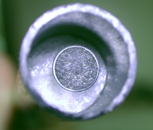
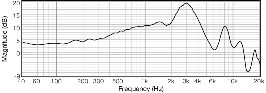
I pinched the idea from the human ear, which use this to improve the resistance to wind - the human ear canal is about 2.5 cm long, with a closed end at high pressure (the eardrum) and the air interface at low pressure. This gives a peak in the frequency response when this length is ¼ wavelength in air, which happens to be about 3kHz3.
You wouldn’t want to do this with music, but it gives me a little bit more punch and directionality, and greatly reduces susceptibility to wind. I may use a lavalier artificial fur windgag over the open end to minimise wind noise further.
-
Yaesu specify the CT-44 adapter for FT-1DR, FT-2DR, FT-3DR, FT-60R, FT-70DR, VX-3R, VX-8DR so by implication the pinout should be the same for all those rigs. My FT3DE is the European version of the FT3DR, the connection is the same, it appears. ↩
-
Having groused about extra connectors in the field, I used CAIRO so I don’t have to make a mic for every rig. ↩