Emcomms Experimentation And Enquiry
NB this is the author’s personal opinion, not the view of the Isle of Avalon Amateur Radio Club
To most UK radio amateurs, Emergency communications means Raynet-UK. I’m looking at this from a point of view of technical curiosity, I want an answer to the question
In a SHTF power, internet, mobile phone and landline network down scenario, what sort of messages can you send via Amateur Radio
tl;dr answer - voice comms and roughly the capability of Multimedia Messaging Services (MMS)
I’m leaving the big picture as to under what circumstances any of this matters to later, the short answer is probably not so much in the UK.
Emcomms modes
Voice procedures
Google will probably find you Raynet exercises on a local repeater, voice comms are the bread and butter of emcomms. You need to be disciplined to work an emcomms net, and practice makes perfect. I am not a strong voice operator and I don’t do repeaters. That isn’t to disparage the work and dedication of people who train to do this, it’s just not my bag, or area of competence. Raynet voice is mainly a VHF/UHF local area FM thing, using repeaters as required, though there is a group Raynet-HF, which looks at NVIS and DX operating using HF.
I am interested in the technology, art and practice of data communications for the sort of message passing used in emcomms. To learn enough with a group of like minded people to be able to take part in something like this competently, or to learn enough to know that I don’t know. To qualify which apply from
lead, follow, or get out of the way
I do not expect to lead. It’s possible that get out of the way is the answer, better to learn this ahead of time ;)
data communications
Why datacomms? from Jeffrey Kopcak’s NBEMS presentation
When compared to voice communications, digital can be:
Faster: Transmit more words per minute.
Reliable: Greater distances. Poorer conditions. Forward error correction (redundant encoding to reconstruct lost data without retransmission).
Kopcak goes on to give examples of the difference:
Short messages suited for voice:
- Patient transport - romeo 5 - has arrived at Lakewood Hospital.
- Patient 176008 status is now green.
Not suited for voice:
- Lists of patients.
- Descriptions of prescription medications.
- Lists of supplies.
- Directions to a location.
- Contacts and phone numbers.
Right off the bat the difference between VHF and up and HF comms needs be acknowledged. Roughly speaking, HF suffers from impulsive noise, higher background noise levels, interfering carriers and fading. HF typically uses SSB even in datacomms transmission, which gives rise to frequency offsets in the recovered audio. But it has a much longer reach than VHF/UHF.
What this is not about - VHF/UHF FM - vive la difference
VHF/UHF is more local, signal to noise ratios are much cleaner, it doesn’t suffer from fading unless mobile, and is a much better fit to the local area group teamworking of a typical emcomms situation. FM modulation is often used, which doesn’t give frequency offsets in the recovered audio, and has other advantages1 for people not trained in voice communications protocols. Which is why Raynet-UK focus on VHF/UHF.
At VHF/UHF for data there’s something to be said for a packet radio local area network, using a standalone BBS on a AX25 node like BPQ32 on a Raspberry Pi. You don’t need to use TNCs, Direwolf will run very well on a Pi and can work as a KISS TNC using an external soundcard or wired to a rig’s USB soundcard. You get decent text comms and the capability to share files, albeit at the slow 1200 baud data rate. Direwolf can do faster rates, but you need to get access to the received signal before FM de-emphasis to get up to 9600 baud. AX25 does routing and net control for you provided users keep the network load below about 30%. It’s established, tried and tested technology.
What this is about - HF SSB modes
At HF the go-to software is FLdigi, part of Narrow Band Emergency Messaging Software. There’s no law saying you can’t use this on VHF/UHF, but the difference is that packet works well on VHF/UHF FM, but the AX.25 overhead makes packet radio really slow and painful on HF if you have noise and fading. Packet isn’t a great option on HF, though it can be done. The price you pay going to FLdigi is in usability and the need for net control. 2.
Other countries can use Winlink and this is referred to in the IARU Emergency Telecommunications Guide but due to the onerous third-party traffic restrictions in the UK I will look at alternatives.
Emergency datacomms falls into two categories, text and images/data. This is narrowband technology, and it is severely limited. What text datacomms can do for you is give you accurate (and if necessary verifiable) transmission, this is hard to do with voice.
FLDigi: - pick a mode, any mode…
 FLdigi is the Swiss Army knife of digital modes. You can use any one of about 70 modes and sub-modes, and therein lies the problem. Both stations need to use exactly the same mode3/sub mode.
In theory you can use the RxID and TxID buttons to keep the two ends in harmony with this, but we have not been able to make this work reliably (there is a frequency offset of 140Hz between readout on our rigs, some modes are more tolerant of tuning errors than others. There’s just too much choice here. There is some guidance on mode selection in this PDF. It is possible to set FLDigi to mask unwanted modes, which makes these menus a lot less daunting. TxID adds about a second to overs, I’d make a case for setting it when you change mode but leave it off in a net otherwise. You can recognise the sound of some digital modes by ear but life is made a lot easier if you only have to tell a few modes apart.
We got some pointers from Raynet-HF to favour the MT63 mode(s) in good conditions, which are tolerant of frequency errors and reasonably fast, though the interleaving does give a delay. When signal to noise is poor, down to -10dB then Olivia 16/500 will work down to those levels but the speed is slow, close to typing speed. This at least narrows down the field somewhat.
Modes we use
- MT63-2kL - default mode when signals are good. reasonably fast, tolerant of frequency offsets
- Olivia 16-500 and 8-500. Good for poor HF conditions4, will work close to noise floor. Slower, and about 6 sec latency
These are the modes we are experimenting with at the moment (Q3/Q4 2020). There isn’t much UK established practice in terms of data nets, and this is self training in the art of wireless telegraphy so we may change in the light of experience. MT63-2KL is a wide mode, occupying the full speech frequency range. This is acceptable on 10m in a low point of the sunspot cycle with little or no adjacent radio traffic, but we will have to review this for use on more crowded bands.
Tradeoffs, tradeoffs : Speed, delay, tuning accuracy, image capability
Basically the choice is on speed, but also latency, usability and finally the possibility of image sending. Some modes, like Olivia, perform outstandingly well in noisy channels with weak signals, but they are slow. Some modes are fast, like the higher BPSK variants, but don’t tolerate slight tuning errors, which make them tough to use in a net. Only a few modes cope with pictures, and here it is a question of do you want small colour images or large B/W ones?
Centre frequency or dial frequency?
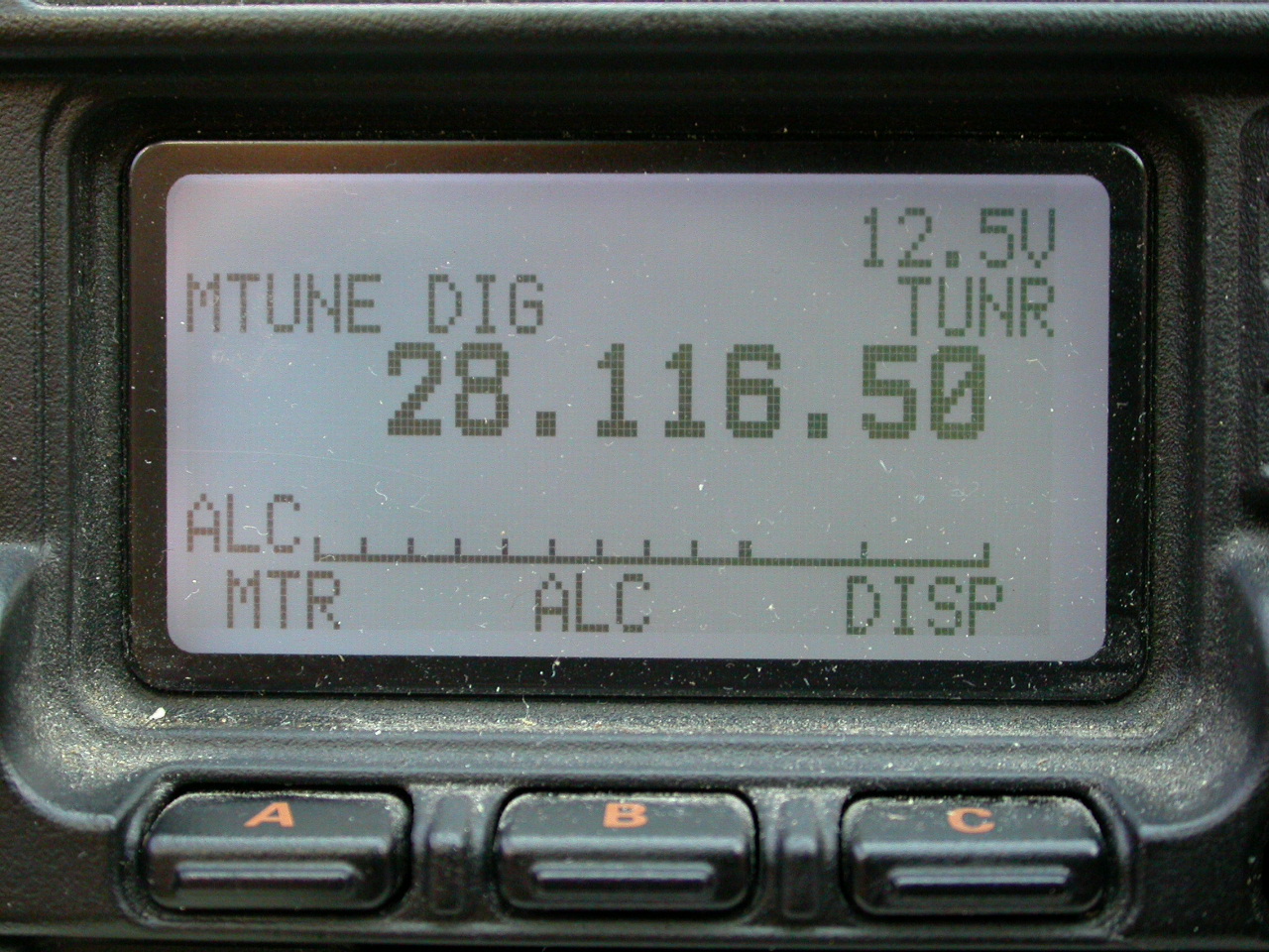
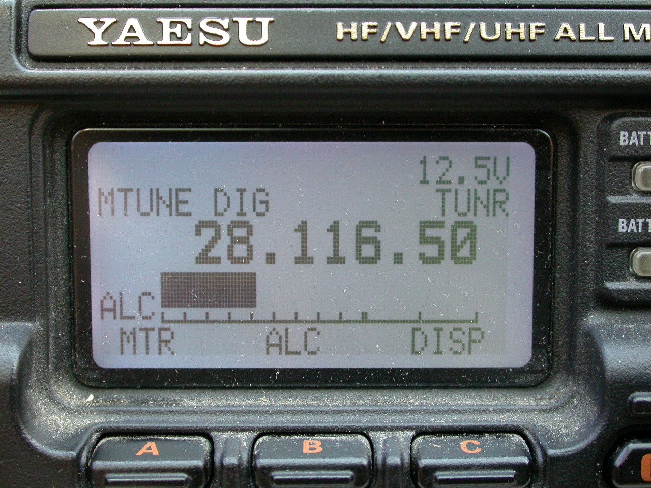
 We are operating on 10m, 28.118 MHz. Digimodes are sent using SSB model, typically USB. There is confusion from the off because a rig set to show 28.118 MHz will never transmit on that frequency because it is the suppressed carrier, all the action will be 300 to 3000 Hz higher than that. Which is a right pain, so if I want to radiate an Olivia16/500 signal on a centre frequency of 28.118 MHz I have to set the radio dial to show 28.1165 MHz and then tell FLdigi to centre its modulation on 1500Hz audio frequency. The rig will take that 1500Hz and add it to the suppressed carrier to make 28.118 MHz. This is tiresome enough when you have time to think about it. It’s compounded by the fact that other pairs are possible5 for exactly the same result. Adding insult to injury, operators who use Ham Radio Deluxe enter the frequency they want their signal radiated at, without having to bother with dial frequency + audio offset frequency malarkey. So a HRD op would enter 28.118 MHz and HRD will select a dial frequency and audio offset automatically. You pays your money and you takes your choice…
Connecting the rig to the computer
The easy way - buy a new rig, or use a modern one
If you have a new rig with inbuilt USB audio then you connect the rig to your computer and off you go, job done. You do need to select the right sound card in FLDigi and tell it what rig you have but after that you are ready to go. You shouldn’t be able to overdrive6 the rig, provided the manufacturer designed the audio interface competently - 0dBFS should correspond to full drive, just before ALC cuts in.
The hard way - analogue interfacing to the rig
Back in the day there was only the microphone and speaker output, and PTT. You have to pad down the radio output to match the microphone input of the computer, and pad down the line out of the computer to match the microphone input of the radio. This is tiresome and wasteful, but it can be made to work. A series 10k resistor to the signal source and a 1k resistor to ground pads down the signal getting you there or thereabouts. G4ILO (SK) showed you how.
the hard hard way - use a soundcard and CAT PTT.
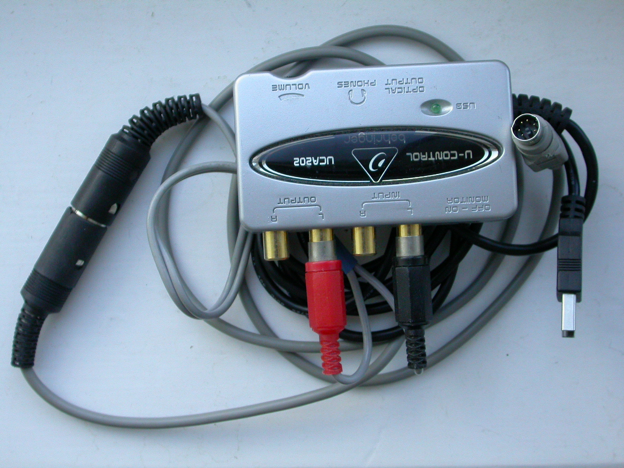
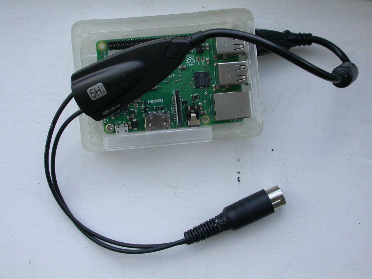
I used this technique, both with a cheap and nasty Ebay USB soundcard and a Raspberry Pi, and a Behringer UCA 202 to a Windows PC. The advantage of the UCA 202 is that it is good, it is cheap, it is common, it is line level in and out so you can wire the radio speaker to it, and it suits the next method well where you can wire the line out of the UCA202 straight to the data in pin of the data socket, which is in fact a fixed level audio socket.
Be warned that it works fine to use non-transformer isolated sound interfaces on equipment powered by separate mains transformers/wall warts. It is a not a good idea to omit isolation if everything is powered off a single 12V source because you get significant ground lift on TX due to the high currents and finite wire resistance. If you’re lucky you get a little distortion but it works fine, if you’re unlucky significant current flows through the sound card/rig printed circuit boards and burns out some fine ground trace.
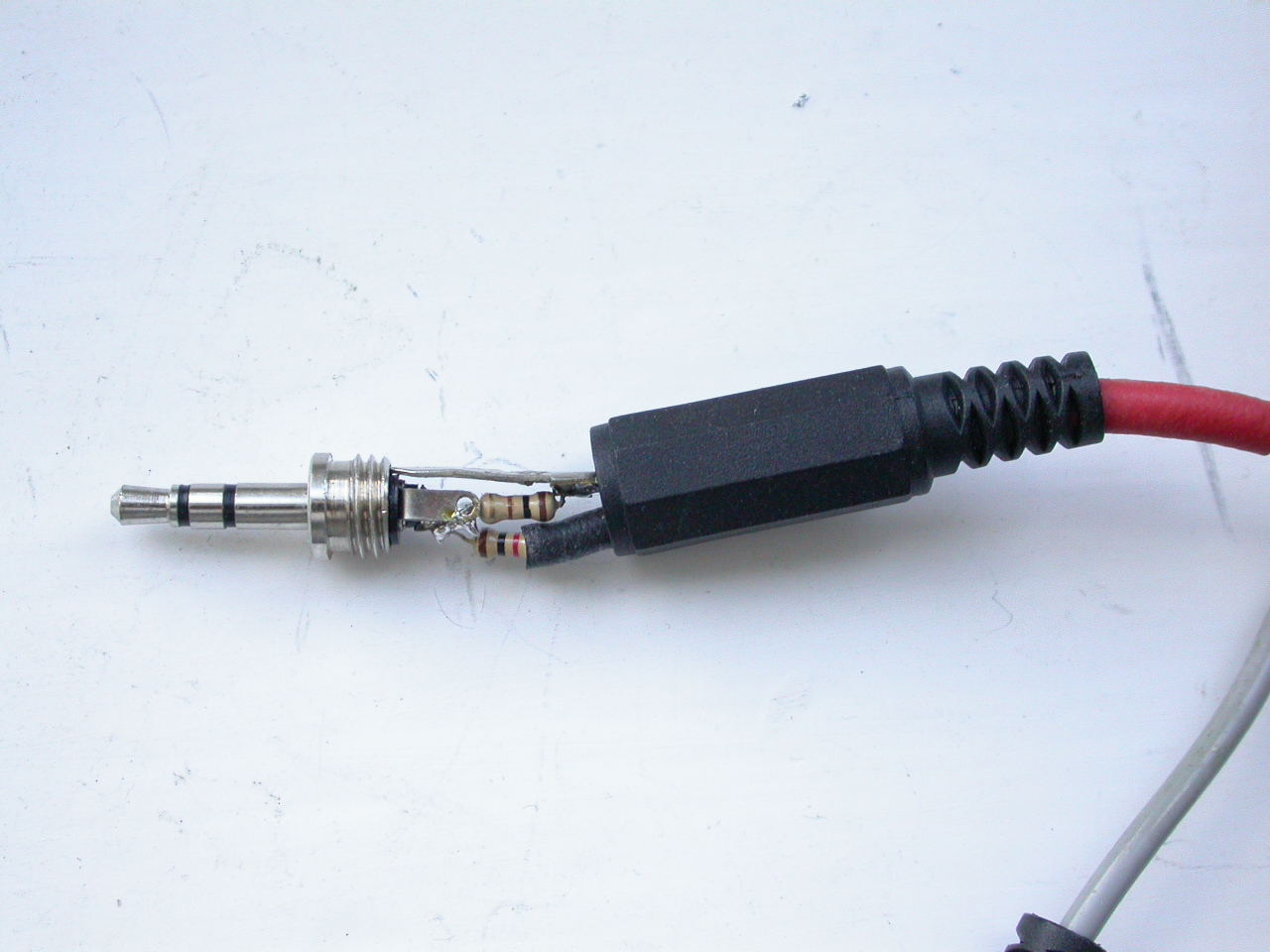
In the case of old rigs like the FT897 I use, there are two ways to get an analogue interface for audio to the rig, one using the mic socket, but preferably go for the other option using the so-called 7 ‘data’ socket on the back. That saves padding the computer audio down to microphone level only for the rig to have to boost it again. Sadly audio-in of most computers tends to be a single mono mic level input that wants up to 10mV and has an input impedance of about 7k, there is often 5V fed via something like a 6.8k resistor to power any attached electret microphone.
You need to attenuate typical speaker level audio from the rig by about 20:1 to work OK. You don’t want to overdrive the rig so the ALC cuts in - in the FT897 that sensitivity to the data socket audio can be adjusted independently of the microphone level, which is a good thing.
the easy hard way - use a dedicated audio interface
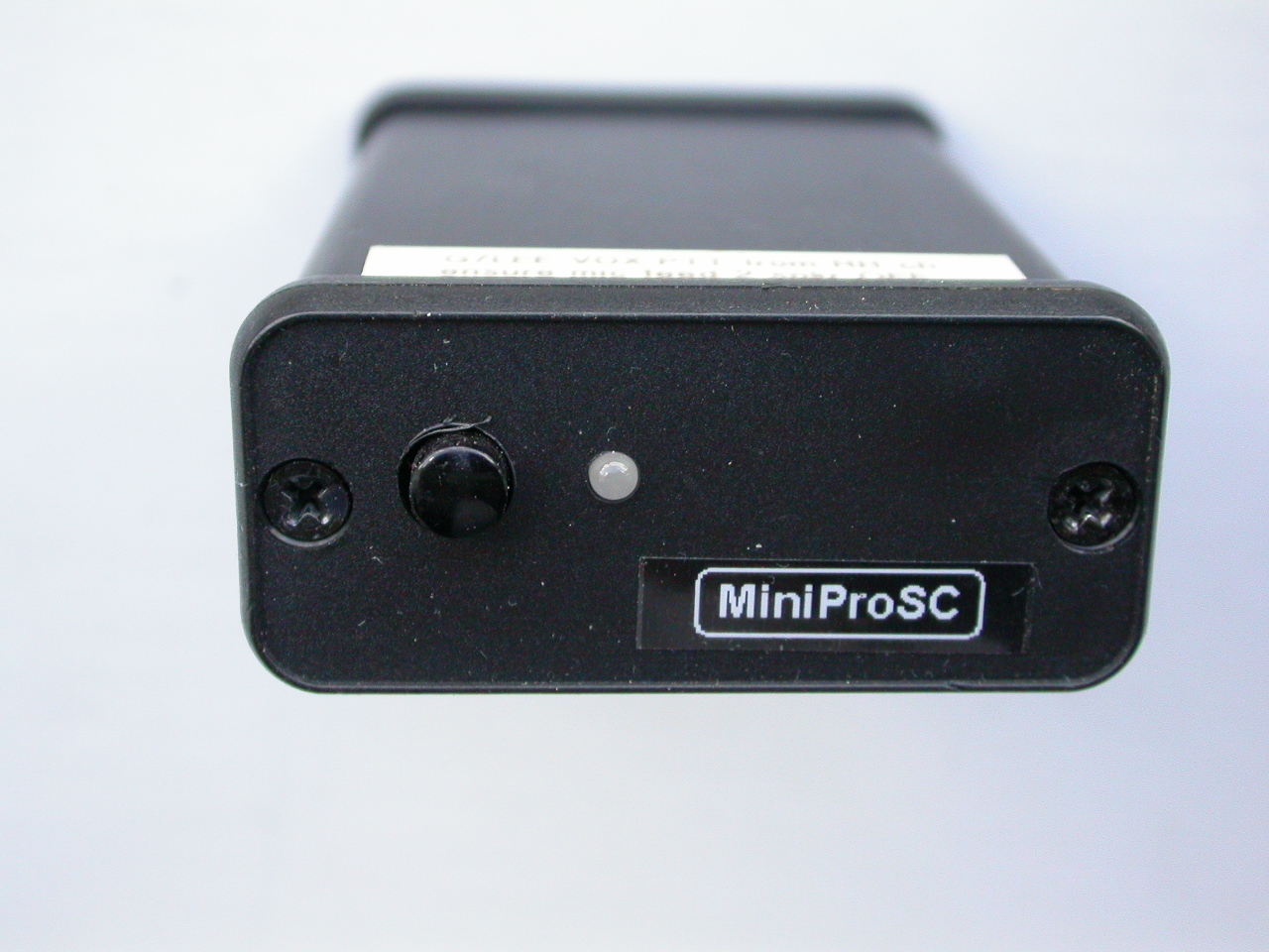
Or you can use a dedicated audio interface like a Rigblaster, Signalink or the G4ZLP interface. Rigblaster and Signalink are US made, they are fine products but you pay a premium, G4ZLP is from the UK as you would guess and is cheaper. I use the MiniPro SC. Confusingly, the data interface to an amateur transceiver is in fact a slightly standardised audio interface. You need a separate RS232 or USB interface for control of the frequency, mode, and sometimes PTT. Plus a way of telling fldigi all the details of where this is, what transceiver is at the end of it, and what data rate to use on the link. Lots of stuff to get right - be methodical and take your time. The advantage of using dedicated interfaces is they generally sort PTT for you audio-derived from the right audio channel, so you don’t have to get CAT control working with one of those interfaces if you are OK with tuning the rig by hand. If you use a sound card instead, you either get to build a VOX for the right channel yourself, in which case where do you get power from, or you get to use CAT PTT. I have found that works OK, but if you have RF feedback you can end up with the rig stuck on TX if RF blocks the CAT connection. Or use VOX on the transceiver, which can be finicky and error-prone to set up, because it can be slow to respond to the incoming signal.
Analogue interfacing - setting levels right
Interfacing your computer to the rig is the main source of pain with digital modes, particularly using an analogue interface with old-style rigs because you have to line levels up else you get horrific splatter.
With all analogue interfacing you have the problem of several places to set drive level, they all interact. Start with the interface levels in Windows using Sound settings, remembering to select the sound card connected to your rig, not the general purpose sound card. In Linux you get to wrangle ALSA or PulseAudio. A good starting point for computer output level settings is between halfway to max and up to the max. For the mic input use a lowish gain and take out any extra boost. You’re feeding this from a speaker level output, you aren’t short of signal level at all. The lower the gain you have on the mic input the less chance there is of RF feedback getting into the signal path and distorting the signal. The radio volume level should be set to about 10 o’clock if you are using the speaker out.
You then get to set the mic gain on the rig, and switch off all compression, DSP, noise blanking etc. Some rigs have a separate menu gain setting for the mic socket and the data input on the back. This is a good thing, but not so much if you don’t know it and drop mic gain to 0 and scratch your head to the effect of “why doesn’t this darn thing make any difference?”. You adjust this so that ALC just comes on, then back it off a little so the ALC goes off. Sadly on some rigs eg my FT897 if you set this right for 20W then the ALC comes on if you drop power to 5W, without touching the audio drive level. So line up at the desired TX power level.
The radio and computer level settings tend to be a little bit coarse for setting up peak levels and ALC - FLDigi does have a facility to fine-tune the audio out drive level in 0.1dB steps which helps you get this right.
the gonzo method if you have no interface
I can’t really condone this sort of thing, but some modes will work holding the mic up to the speaker both rig and PC, but there is a minimal level of professionalism we desire even as radio amateurs, so we don’t approve of that. But if you’re stuck in an emcomms situation, well, just saying… Modes like MT63 seem to work OK with that, not all will.
Pictures - what part of narrowband does Sir not understand?
 Ahh, pictures. We’ve been spoiled ever since they invented broadband. I am old enough to recall the first time I saw a picture downloaded on a computer, back in the days of Compuserve on dial-up. Back then screens were 640 pixels across and 480 high, so you could see a 320 x 256 image on a large part of the screen. Nowadays, though the picture hasn’t changed, the physical size of the image has shrunk because screen resolutions have gone up. Narrowband images aren’t really going to light your fire, and having to squint at them doesn’t make thing better. The image of the Tor is 320x256, about right for Martin 1 SSTV mode. It’s probably rather underwhelming on your screen.
 Only a few FLdigi modes support pictures natively. The obvious way to send a picture in the internet age is to send it as a data file, so I set up a 10kB picture file and asked FLAmp to send it. FLAamp is designed to encapsulate the binary file suitably, it lets you send the file and the receiver to ask for retransmissions of any blocks that were lost in transmission. It does that in the same way as email does - it base-64 encodes the image into a string of text characters. FLamp told me it was going to take 12minutes and 4 seconds to sent this file using MT63-2kL. This view isn’t worth the climb, so I declined.
For comparison, using QSSTV in Martin-1 mode took about 2 minutes to send a similar file, and because this is an analogue format it doesn’t have the horrendous digital artefacts that heavy JPEG compression did. Using QSSTV in DRM mode B 4QAM for a 50k version of the file said it would take 6 minutes. So using SSTV would score, particularly analogue SSTV, if the path allowed it. DRM lets the receiving station request lost blocks, the end result should be the same as the original file.
 But you need a different program, and realistically that’s not going to happen. What can you do with NBEMS? FLDigi lets you transmit sort of SSTV images but in the specific modes that support it. They are sort of SSTV in that the received file is subject to the slings and arrows of propagation, they are analogue in that respect. Minor sample frequency differences between sound cards cause this sort of Leaning Tower of Pisa effect, though you can calibrate that out beforehand. It’s quite remarkable, given this is the difference between crystal oscillators!
You lose some signal quality, even in an image from a direct audio recording
 The manual says
Tuning must be very accurate, and the software will not tolerate differences between transmit and receive frequency.
They really aren’t kidding. This is a tough mode to interchange pictures with, I would say it is impractical in our experience. It is fine if you have 2m talkback so the sending station can abort and retry as the Rx station fine-tunes to catch the sync signal at the start, so it was time to investigate other picture modes. The two others I could find are IFKP and Throb.
You can see some of how this works with the shortwave radiogram project. MFSK images take a long time to send, Typically WxH (in pixels)/1000 secs (BW) and WxHx3/1000 secs (colour) For 320x256 that’s about 4 minutes.
The big picture - when would this be relevant?
What sort of scenario would cause such a full-spectrum outage? We’ve had widespread power outages in the Somerset area due to flooding, mobile operators have power backups ranging from about 30mins for residential areas to generator backups, it depends on the site importance. And of course if the cabinet is under three feet of dirty water that’s not so good.
The emergency services use Airwave, a TETRA trunked professional mobile radio solution independent of the mobile network with its own infrastructure, and presumably have adopted suitable backup power solutions for their sites. Worryingly, the bean counters have decided this should be migrated to the Emergency Service Network, EE’s mobile 4G network, which is not without controversy and criticism from the public accounts committee who have observed that saving money is going to cost the Home Office a fortune - £3billion overspend and a three-year delay.
Other things could be a Carrington Event knocking out satellite communications and infrastructure generally. Best make a tinfoil hat for your transceiver, don’t leave it plugged into power or the antenna and preferably keep your go bag in a biscuit tin/ammo box buried in the garden then…
So it’s hard for me to see a scenario where this would be required, but I am interested in what could be done. It’s important to note, however, that effective emergency communications is probably more about practice, common standards and knowing what not to do and what to do when rather than technology. However, I have struggled to find any summary of used tech solutions and what they can do. We have performed some experiments to see what is possible.
culture, politics
Britain is a small country and not quite so much in the line of fire of large area natural disasters as the US, where emcomms is a bigger part of how amateur radio operators view their place in society. The culture is different. Political differences/spats meant that for decades UK amateurs did not speak with one voice, split into two factions, Raynet and RAEN, which were combined again about five years ago, but the split did cause an image problem and can’t have made life easier for user services. Selecting the link from the local groups listing on the Raynet-UK website to the local group to Bristol & Somerset Raynet at
Raynet-UK aren’t the only people using Amateur Radio for emcomms, 4x4 response teams eg Wessex4x4response also use some Amateur gear with licenced operators, usually Foundation level meets their operational needs.
-
for example the squelch noise tail helps inform other users that the transmission is over and the channel is free, on SSB you have to mark the end of your transmission with ‘over’ because otherwise people won’t know. ↩
-
AX25 does all the routing between stations automatically, and retransmits packets that are lost. Providing your total traffic doesn’t load the shared channel more than about 30% it works well and you have no need of a net control station in packet radio. See Zielinsky, 2003, “Effective throughput of AX.25 protocol” DOI: 10.2478/bpasts-2013-0068 ↩
-
Mode is also called modem in some parts of the FLDigi documentation, particularly in FLMsg. It is the particular form of digital encoding used, eg BPSK31 or Olivia 16/500 ↩
-
WB9ROL’s QST article indicates Olivia 8/500 is 30 wpm (62.5 baud) and 16/500 is 20wpm (19.5 baud) ↩
-
set the dial to 28.117 and FLdigi to a audio frequency of 1000 Hz and you will get the same result. It pays to set the audio frequency somewhere in the middle of the audio passband, which favours 1500Hz, though the mental arithmetic is easier if it were 1000Hz. While you could send BPSK32 at a dial frequency of 28.1155MHz and a audio frequency of 2500 Hz some of the wider modes would fall out of the TX passband. An of course nobody wants to hear Morse screeching out at a tone frequency of 1500Hz. You set the default audio centre frequency in configure -> Misc -> Sweet Spot and thankfully there is a separate setting for Morse. ↩
-
excessive signal levels are the bane of digimodes, and analogue interfacing needs to be lined up right to prevent this. ↩
-
so-called data because it is in fact a purely audio interface, not digital ones and zeros. It is called data interface because when it was inaugurated in the 1990s it was designed for data encoded onto an audio stream. This was fine and dandy until people started to use CAT control of the transceiver, which was a real honest RS232 data interface with ones and zeroes, now what the heck were they going to call that now the audio interface to the rig had been mislabelled ‘data’ ? ↩