
Testing a 1:1 Guanella current balun
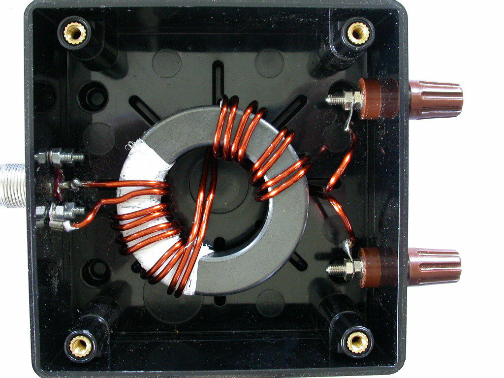
One of our members has crafted a QRO balun for our upcoming attempt at Exercise blue Ham on the 60m band. This is a 1:1 Guanella current balun (Theoretical treatment on owenduffy.net). I ran some tests using an antenna analyser, based on W8JI’s basic balanced quality test for current baluns
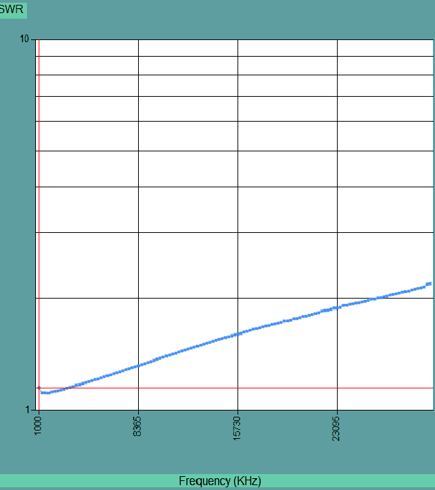
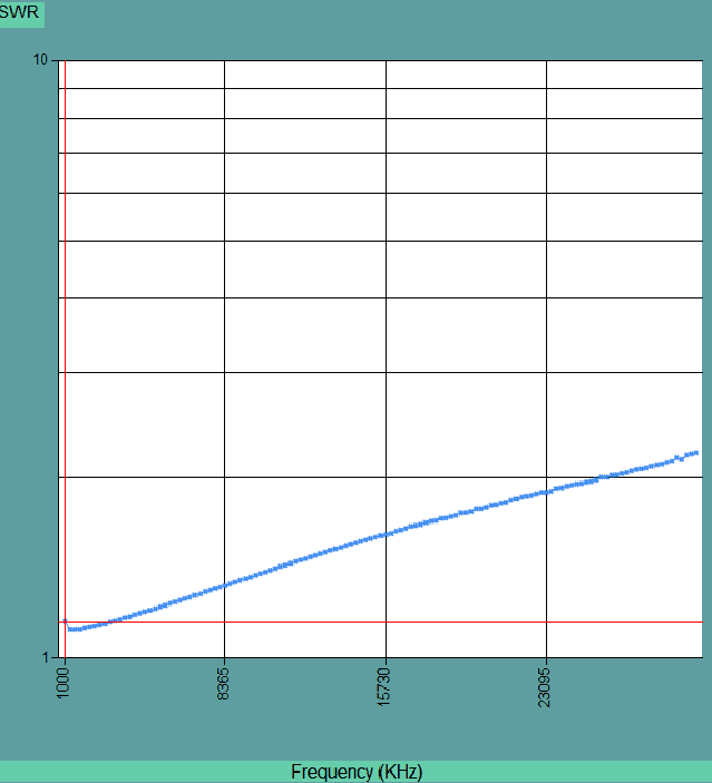
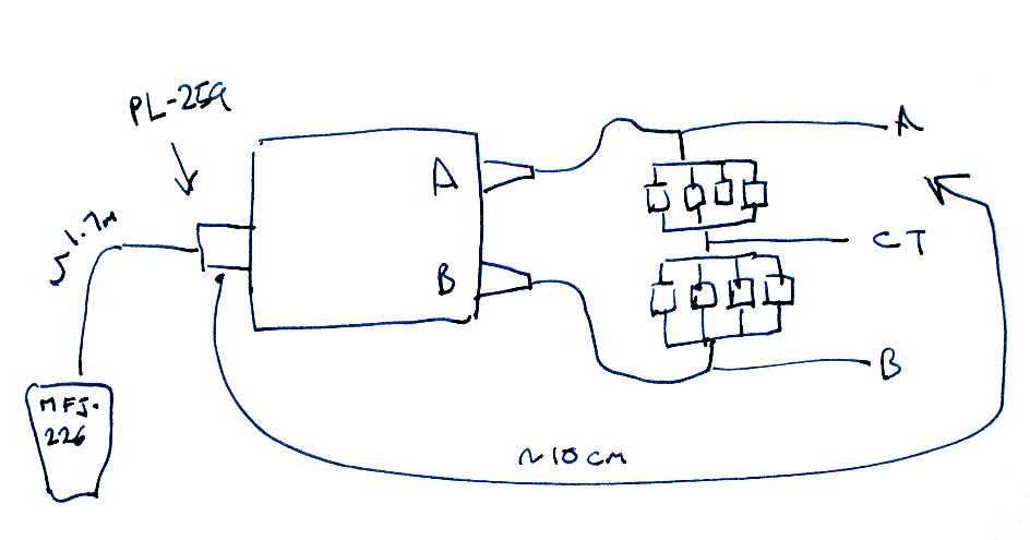
I connected a MFJ-226 antenna analyser to the balun SO-239 connector via 1.7m of RG58C/U, and tested SWR with the other end open and shorted, with the analyser set to sweep between 1MHz and 30MHz. The open and shorted case were SWR > 10. From G8JNJ’s experiments this implies through loss is likely to be < 1dB.
Eight 100ohm 1/4 W resistors were used, made up as two lots of four in parallel, making two 25R resistors. These were then wired in series to the binding posts, making up a centre tapped 50 ohm load.
For a sanity check the 50 ohm resistor was presented to the analyser without the balun and a measurement of SWR taken at 5.3MHz (close to the operating frequency at 60m). The SWR was observed at 1.03, confirming the resistor and the cable were serviceable.
A 10cm lead was taken to the input PL259 on the balun, and the other end shorted to A and B as per W8JI’s article.
and for a sanity check the input ground was shorted to the centre tap, which was very similar to the above two traces.
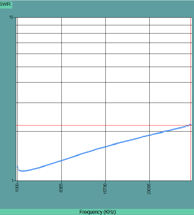
This meets W8JI’s basic balanced quality test. Note that the Type 31 ferrite mix used is 1designed for use up to 10MHz in this sort of service.
It’s really hard to see the small changes in SWR over the operating frequency range, so I did a series of single-frequency tests
| Frequency | SWR term | SWR term & A grounded | SWR term & B grounded | SWR term & term CT grounded |
|---|---|---|---|---|
| 1 | 1.6 | 1.22 | 1.16 | 1.17 |
| 2 | 1.12 | 1.15 | 1.12 | 1.13 |
| 3 | 1.14 | 1.16 | 1.15 | 1.15 |
| 4 | 1.17 | 1.18 | 1.17 | 1.18 |
| 5 | 1.20 | 1.21 | 1.20 | 1.20 |
| 6 | 1.23 | 1.24 | 1.23 | 1.24 |
| 7 | 1.27 | 1.28 | 1.27 | 1.27 |
| 8 | 1.30 | 1.31 | 1.30 | 1.30 |
| 9 | 1.34 | 1.35 | 1.35 | 1.34 |
| 10 | 1.38 | 1.39 | 1.38 | 1.38 |
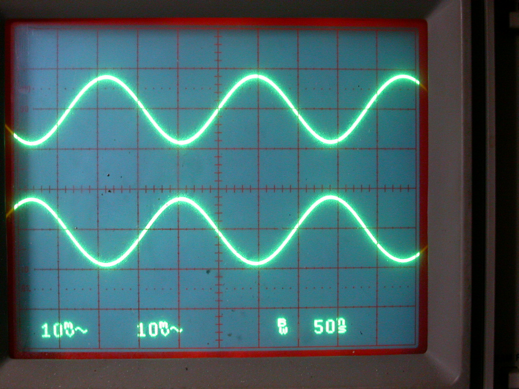
The job of a balun is to present a balanced signal to the load. Wiring the scope probes ground to the load centre tap and looking at the two binding posts shows a satisfyingly balanced signal
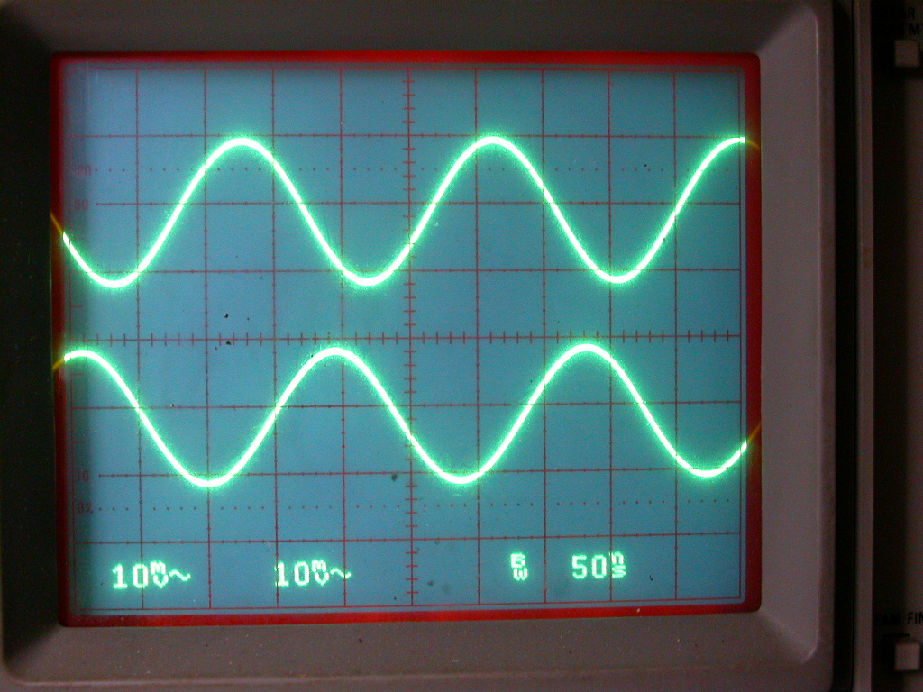
Referring the scope ground to the balun input ground shows decent but not perfect balance. Although the probes are the same type and were compensated first I cannot guarantee the input capacitance of ~ 10pf matched, so the current balun may just have been doing its job into a slightly unbalanced load.
Richard G7LEE